
TM 9-4120-402-14
4-5.
INSTALLATION INSTRUCTIONS. - continued
NOTE
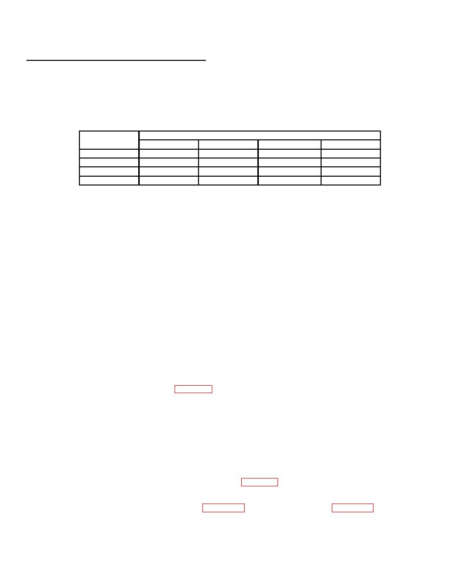
Voltages should be approximately as shown. If voltages are not within ten volts of those
indicated on chart, disconnect power. Locate and correct problem.
Table 4-1. Connector (P4)
Measure
To Pin
from Pin
A
B
C
D
A
N/A
208
208
120
B
208
N/A
208
120
C
208
208
N/A
120
D
120
120
120
N/A
(e)
Check that MODE selector rotary switch is OFF.
CAUTION
Use disconnect switch (NOT POWER CABLE) to disconnect power to unit. Damage to cable
connector pins will result if cable is used.
(f)
Disconnect power to cable.
(g)
Connect cable connector P4 to connector J4 on air conditioner.
(h)
Check that air conditioner MODE selector rotary switch is OFF.
(i)
Connect power to air conditioner.
NOTE
For more information on air conditioner installations, refer to MIL-HDBK-116 Environmental
Control of Small Shelters.
The following steps require two people. One must be at control panel. The other must be in
position at rear of air conditioner to see condenser fan rotation. (Condenser fan can be seen
through condenser air outlet grille, figure 1-2, item 18.)
(j)
The person at control panel should turn MODE selector rotary switch to VENTilate and
immediately back to OFF/RESET.
(k)
The person at rear of unit should watch condenser fan to determine direction of rotation. Fan
blades must turn toward grille.
(I)
If fan blades turn away from grille, unit power cable is not connected properly. Exchange wires
connected to pins A and B at power source connection and repeat steps (i) and (j) above.
(m) Check unit operation in accordance with Table 4-2, Unit Preventive Maintenance Checks and
Services (PMCS) Quarterly Schedule, item 23.
(9)
See air conditioner wiring diagram, figure 4-10, and electrical schematic, figure 4-11, for additional
wiring information.
4-19

