
TM 9-4120-402-14
4-41. HEATER RELAY (K1) AND DIODE (CR2). - continued
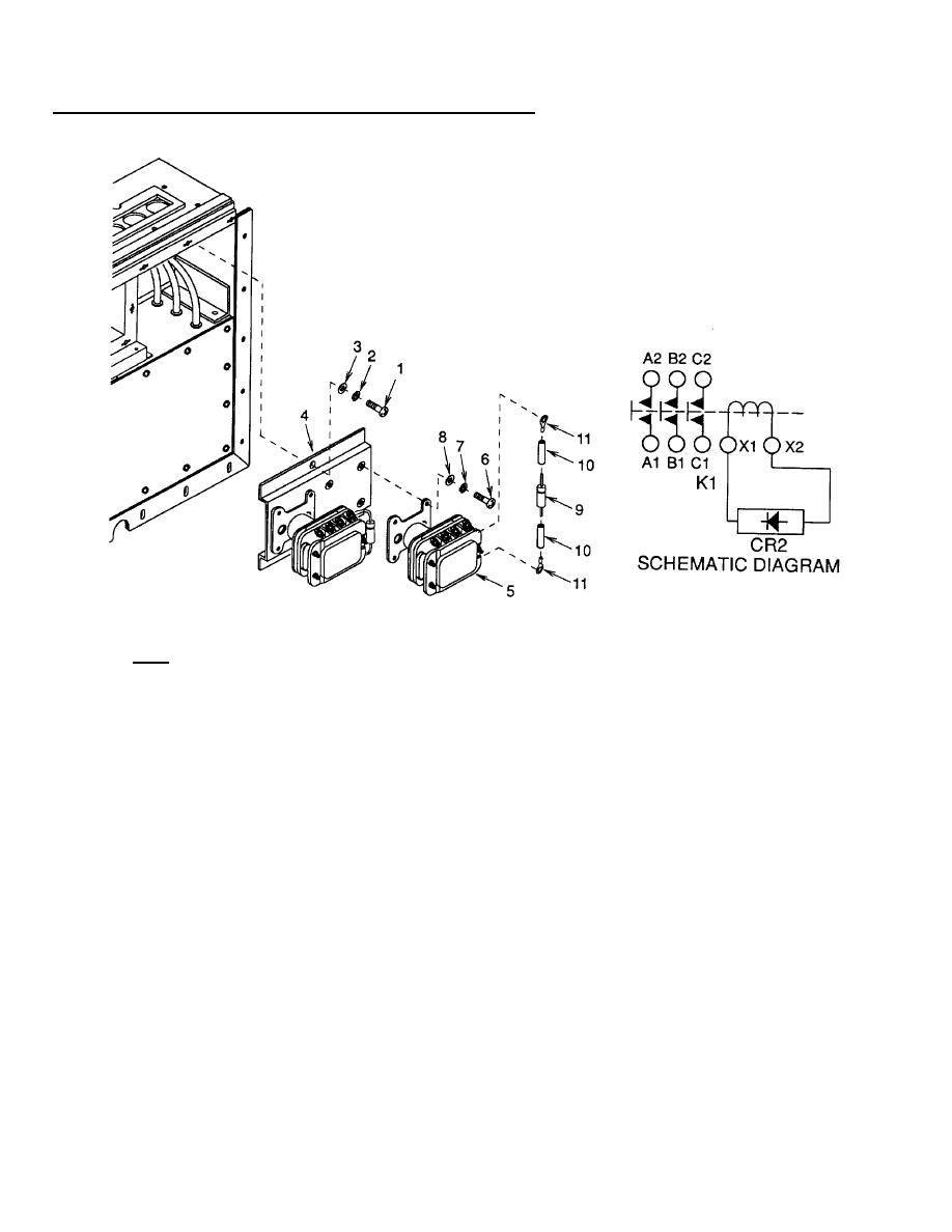
Figure 4-42. Heater Relay (K1) and Diode (CR2)
c. Test.
(1) Compressor start relay (5).
(a) Apply 28VDC to terminals X1 (positive) and X2 (negative).
(b) Check continuity across terminals Al and A2; B1 and B2, and C1 and C2. The multimeter must show
that contacts are closed (continuity).
(c) Remove power. Multimeter must show that contacts are open (no continuity).
(2) Diode (9).
(a) Using a multimeter set to test diodes, connect black lead to band end of diode and red lead to opposite
end. The multimeter should indicate between 0.5 and 1.75 volt drop.
(b) Reverse the leads from step (a) above and check. The multimeter should give no indication.
4-122

