
TM 9-4120-408-14
1-13. LOCATION AND DESCRIPTION OF MAJOR COMPONENTS. (Continued)
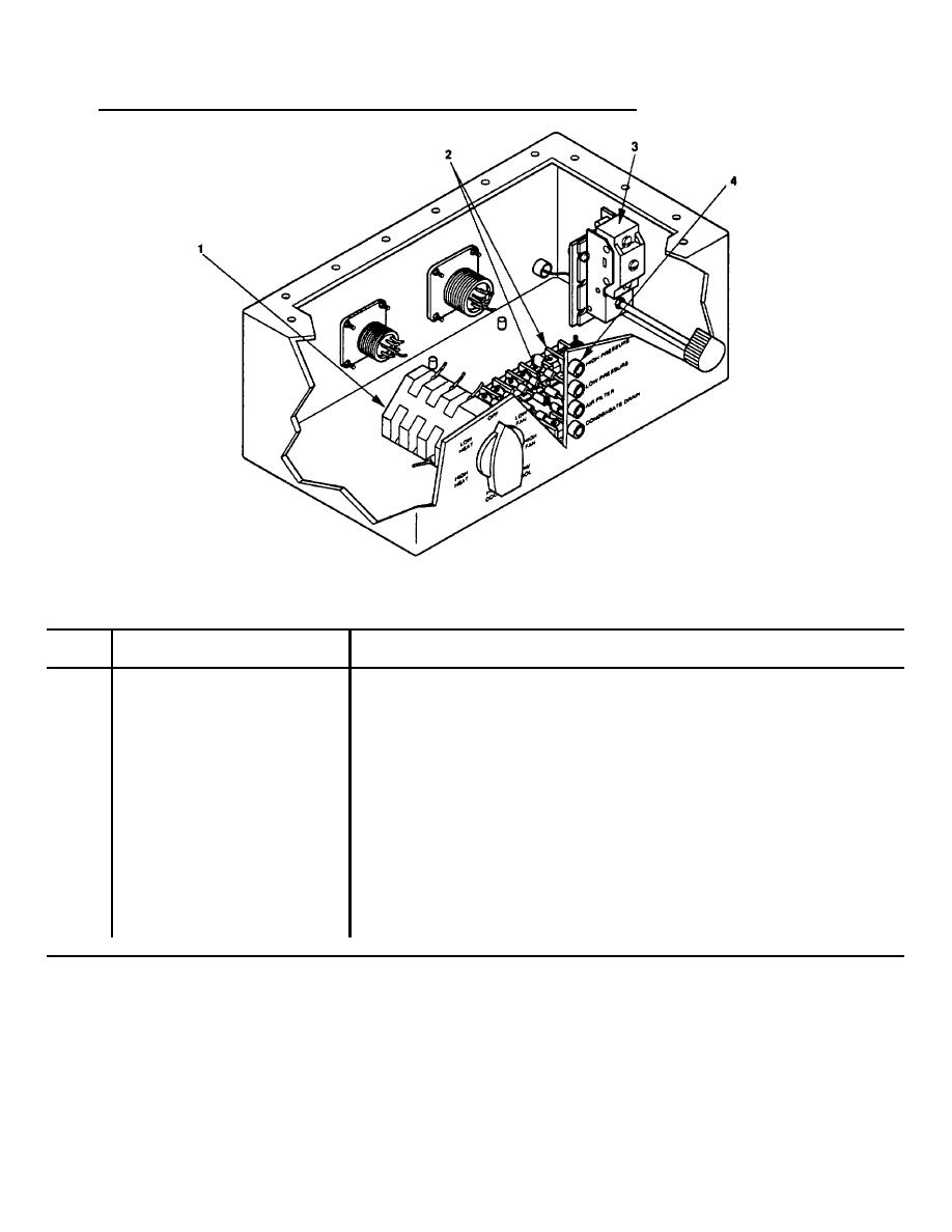
Figure 1-3. Location of Major Components, Control Module.
Table 1-3. Description of Major Components, Control Module.
Item
Item Name
Description and Purpose
No.
1
Mode Selector Switch (S1)
Seven position switch that allows operator to
control the air conditioner modes. The seven
modes are: High Cool, Low Cool, High Fan, Low
Fan, High Heat (Increases evaporator fan speed
only. Does not increase heat output), Low Heat,
and Off.
2
Terminal Board, Single Row
Allows for ease of troubleshooting and repair.
3
Thermostat Switch (S2)
Allows operator to control temperature of
enclosure.
4
Indicator Lights
Alerts operator if a deficiency occurs. The
four indicator lights are: High Pressure
warning, Low Pressure warning, Air Filter
warning, and Condensate Drain warning.
1-6

