
TM 9-4120-408-14
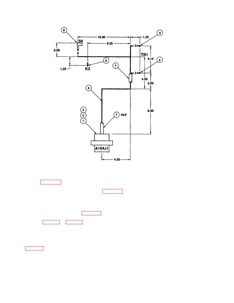
Figure F-1. Wiring Harness A104J1.
PROCEDURES:
a. Refer to Figure H-2 and determine faulty wire.
b. Remove and discard electrical cable clamp (Figure F-1, 2), insulation sleeving (3), and insulation sleeving
(7) from connector (1) and wiring.
c. Remove faulty wire from wiring harness.
d. Cut wire to dimensions shown in Figure F-1.
e. Refer to table F-1 and table F-2 and assemble wire. Mark wire with from to termination designations and
double headed arrow on each end of wire assembly.
f. Install wire in connector (1).
g. Install new electrical cable clamp (2), insulation sleeving (3), and insulation sleeving (7), as shown in
h. Install tiedown straps at 3.00 inch maximum intervals and at each breakout.
F-2

