
TM 9-4120-411-14
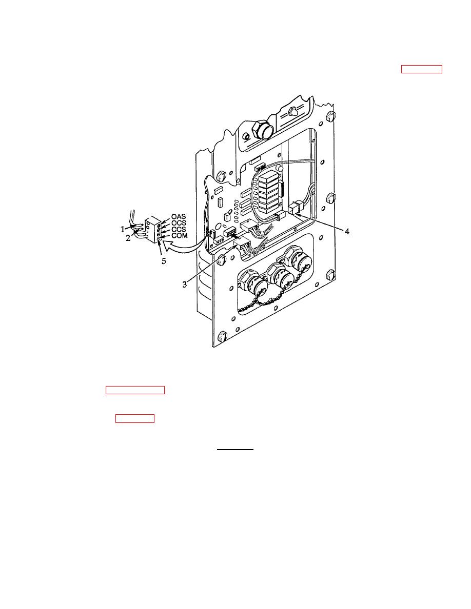
(4) Connect outside air sensor wire lead (1) to TP4 terminal OAS per tag and wiring diagram figure 4-14.
Remove tag.
Figure 4-10. Thermistor Temperature Sensor Test Points.
4.12 GENERAL TROUBLESHOOTING PROCEDURES. Electrical wiring and connections can be tested per electrical
system general repair paragraph 4.16. The following paragraphs describe the procedures necessary to make general
overall tests on specific components in the FDECU.
a. PC Board. See figure 4-9. To test if the logic circuits and output controls have power and are functioning
properly, the pc board will be checked with power connected. Use extreme caution when testing the pc board.
WARNING
Lethal voltage levels are used in operating the FDECU. Be sure to observe
extreme caution when accessing pc board with power connected. Injury or death
can occur if personnel contact any electrical terminal while the unit is connected to
power source.
(1) To make a visual check that the logic circuits have power, check to see if any light emitting diodes (LED's)
are on. If no LED's are on, place the CONTROL SELECTION switch to the REMOTE BOX position and
check that the remote indicator (LED) (D12) is on. If it does not come on, check voltage per the following
procedures.
4-27

