
TM 9-4520-260-13
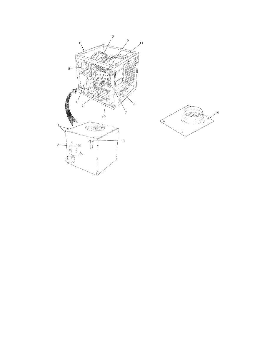
Figure 1-2. Major Components of Model UH48-E Heater (With Top and Side Cover Panels Removed).
i. Carburetor (9). The carburetor meters the flow of fuel to the burner head to achieve efficient combustion. A fuel
adjustment needle enables manual adjustment of flow rate. Solenoid valves control the fuel flow from the float bowl to
the fuel nozzle. Fuel lines carry fuel from the strainer to lice fuel pump and from the fuel pump to the carburetor.
j. Electronic Control Unit (ECG') (10). The electronic control unit controls automatic heater operation. After ignition,
the control unit will start and stop the heater as the thermostat reaches the desired setting. The unit controls the glow
plug, igniter, and fuel heater. Starting and stopping is controlled by relay switching and time delays. The ECU will purge
the system after shutdown.
k. Heat Exchanger (11). The heat exchanger is open to the burner head at one end and contains an exhaust outlet at
the other end. The burning air and fuel mixture heats the heat exchanger walls. A ventilation air blower blows air around
the outside of the heat exchanger and picks up heat before it passes through the warm air louver to the enclosure to be
heated.
l. Motor/Blower Assembly (12'). The blower motor assembly consists of a 28 VDC motor and two blower assemblies.
One blower is mounted on the motor at the rear of the heater and provides air through an air hose to the burner head.
The other blower is mounted to the heat exchanger and provides air around the outside of the heat exchanger. The
heated air passes through the louver to the enclosure to be heated..
1-4

