
TM -94910-387-14-2
6-29. SWITCH ACTUATING CAM ASSEMBLY - MAINTENANCE INSTRUCTIONS
THIS TASK COVERS:
a. Removal
d. Repair
b. Disassembly
e. Reassembly
c. Inspection/servicing
f. Installation
INITIAL SETUP
Tools and Special Tools
Equipment Conditions
General mechanic's automotive tool kit (5180-00-177-7033) Main power source to tester is turned off
4-32
Upper back panel is removed
Materials/Parts
433
RH upper side panel is removed
Cleaning compound (item 3, app C)
Counter pulse switch is removed
Rag (item 14, app C)
References
TM 9-4910-387-24P
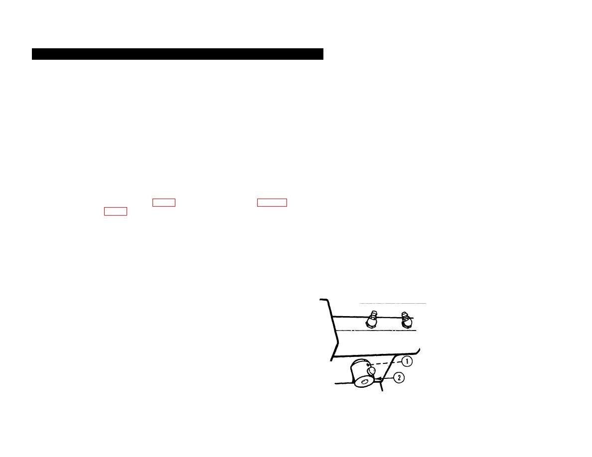
REMOVAL
NOTE Before removal, scribe a mark on the gear shaft on both sides of the
switch actuating cam assembly for proper alinement during reassembly.
1 SETSCREW (1). Loosen.
2 SWITCH ACTUATING CAM ASSEMBLY (2). Remove.
6-453

