
d. Mounting Vacuum Controlled Distrib-
clamp knob. Lower the shaft of the dis-
utors. Secure the universal distributor
tributor into the rubber jaws of the uni-
clamp (2, fig. 5) near the top of the drive
versal distributor drive chuck and secure
column (4, fig. 5). Clamp the distributor
the chuck. The chuck jaws should not be
shaft collet (fig. 16) in the universal dis-
tightened until after the distributor is
tributor clamp with the knurled nut up. Re-
clamped in the universal distributor clamp
move the knurled nut and insert the correct
(2, fig. 5) and the height adjustment knob
bushing (fig. 16) into the collet with the
(3, fig. 5) tightened. If vibration is noted
flange up. Insert the distributor shaft
during operation it may be eliminated by
through the bushing and secure the vacuum
loosening the height adjustment knob and,
control mounting bracket to the stud on the
with the distributor tester speeded up,
collet with the knurled nut as shown in
move the distributor to the right or left as
required for smoothiest operation.
with the clamp locking knob. Loosen the
height adjustment knob (fig. 8), slide the
distributor down on the drive column until
the distributor gear or shaft engages the
rubber drive coupling (7, fig. 5), or uni-
versal distributor drive chuck (fig. 7) and
tighten the height adjustment knob. If the
chuck is used, tighten the chuck jaws using
the chuck wrench (fig. 16) after the aline-
ment is made and the height adjustment
knob is secured. Install the correct
adapter from the vacuum adapter kit (fig.
vacuum hose to the adapter. Mounting of
distributors with the vacuum control at-
tached directly to the distributor is
accomplished the same as mounting dis-
tributors with no vacuum control. See
paragraph b above for general mounting
instructions.
e. Controls. Instructions for connecting,
starting, operating, and stopping the dis-
tributor tester are contained in paragraph
9e.
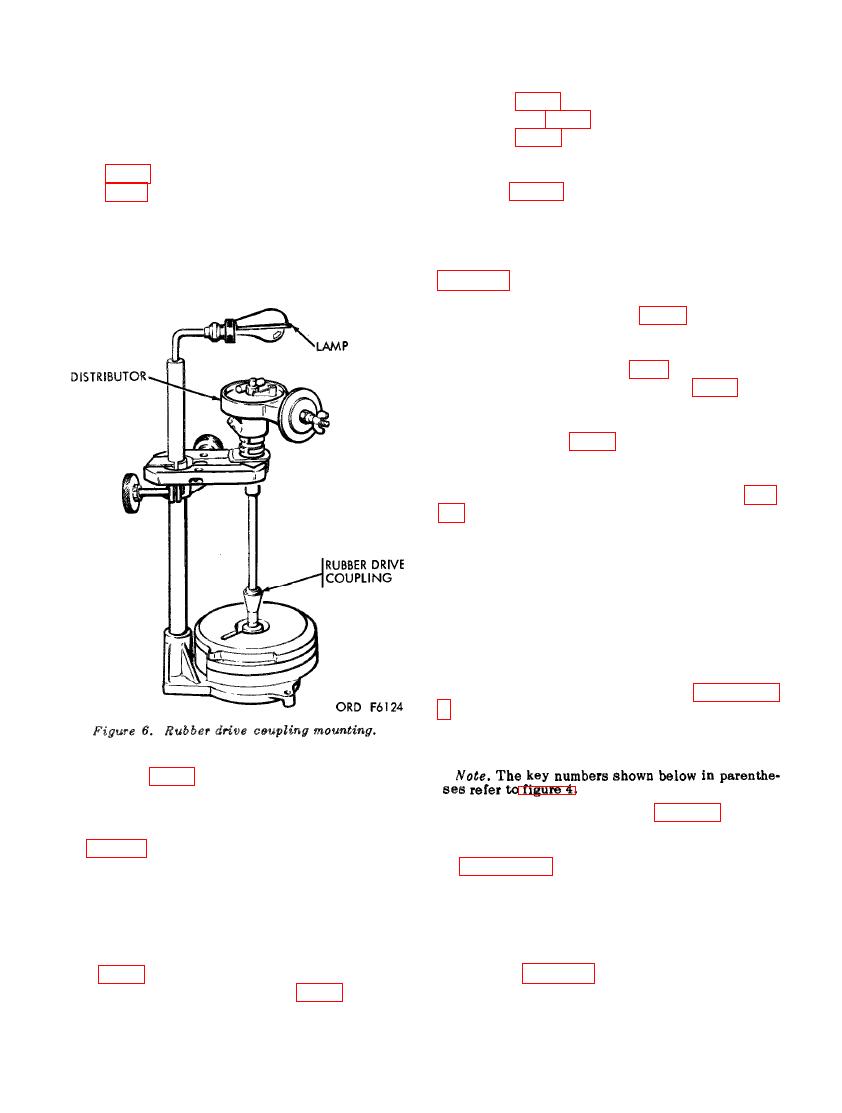
c. Mounting Governor Controlled Dis-
tributors (fig. 6) (with or without Vacuum
Controlled Breaker Plate). Clamp the
machined section of the distributor housing
in the universal distributor clamp as shown
the dwell meter (22), tachometer indicator
in figure 6, press down slightly so the dis-
(18), and vacuum gage (10) as prescribed
in paragraph 9e(1). Put the direction con-
tributor gear will engage the rubber drive
trol switch in the off position and turn the
coupling firmly, and tighten the height ad-
justment knob. See paragraph b above for
power switch (3B) on.
general mounting instructions. If the dis-
b. Set the meter selector (20) to the
"ADJ & 8 CYL" position and connect the
tributor has a vacuum control, install the
cam angle lead (6) to the distributor as
correct adapter from the vacuum adapter
shown in figure 9. If there is no reading
kit (fig. 16) in the vacuum control and con-
on the dwell meter (22), rotate the dis-
nect the vacuum hose (9, fig. 4) to the
tributor shaft until the distributor points
adapter.

