
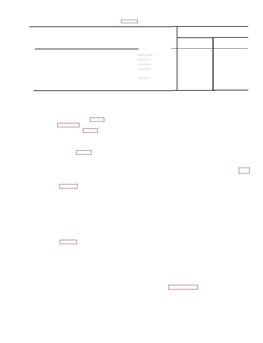
Table 4 - Continued.
(3)
(2)
(1)
Position
Figure No. 32
(b)
(a)
After
Key No.
Before
OFF
18
OFF
250-ohm 5-ampere maximum switch . .
..
.
............
.
24V
19
24V
Battery circuit selector switch . . .
.
.
........
.
20
OFF
OFF
Battery on-off switch . . . . . . . .
.
.
.........
.
S T O P (button
21
S T O P (button
Drive control . . . . . . . . .
.
.
.......
.
depressed)
depressed)
One-quarter speed
22
One-quarter speed
Speed control handle . . . . . . . . . . . . . . . . .
(counter-
(counter-
clockwise)
clockwise)
of the cut-out relay unit will be re-
(3) Cut-out relay unit.
quired. Refer to manufacturer's
(a) Remove the cover from the genera-
l i t e r a t u r e o r p e r t i n e n t publica-
tor regulator (fig. 31) as shown in
tion (s) covering the generator reg-
ulator for this procedure. Continue
ber 38425 (fig. 74) in the top of the
with tests in (4) below.
negative test indicator binding post
(24) and connect the other end to
(4) Voltage regulator unit.
the ground (GND) binding post
(a) Place the 40-ohm 30-ampere maxi-
(10-E, fig. 15). Plug another test
mum rheo-reg switch in the "REG"
lead number 38425 in the top of the
position and connect a jumper cable
positive test indicator binding post
a c r o s s the upper and lower points
(23) and clip the other end on the
o f the voltage regulator unit (fig.
armature (upper points (battery
34).
side)) of the cut-out relay unit
(b) Start the varidrive assembly as pre-
(figs. 33 or 34).
scribed in c(7) above. Turn the
(b) S t a r t t h e v a r i d r i v e a s s e m b l y a s
s p e e d control handle (22) slowly
specified in c(7) above and turn the
clockwise until 3,000 rpm are indi-
s p e e d control handle (22) slowly
c a t e d on the tachometer indicator
clockwise until 1,700 rpm are indi-
m e t e r (3). The voltage reading on
c a t e d on the tachometer indicator
the dc voltmeter (4) should be ap-
meter (3).
proximately 28.2 volts.
(c) Turn the 40-ohm field current rheo-
(c) Stop the varidrive assembly by de-
stat (16) clockwise slowly, until the
pressing the "STOP" button (21-C)
points of the cut-out relay unit close
o n the drive control (21) and re-
move the jumper cable, (a) a b o v e .
cated when the test indicator lamp
(d) I f the voltage reading is not as
(25) lights up. Observe the voltage
specified in (b) above, adjustment
r e a d i n g on the dc voltmeter (4)
of the voltage regulator unit will be
when the points close. The reading
required. Refer to manufacturer's
should be approximately 26 volts.
literature or pertinent publica-
(d) Stop the varidrive assembly by de-
tion (s) covering the generator reg-
pressing the "STOP" button (21-C)
u l a t o r for this procedure. Refer to
o n the drive control (21) and re-
move the test leads, (a) a b o v e .
s t r u c t i o n s for setting the voltage
(e) I f the voltage reading is not as
r e g u l a t o r unit. Continue with tests
specified in (c) above, adjustment
in (5) below.

