
Table
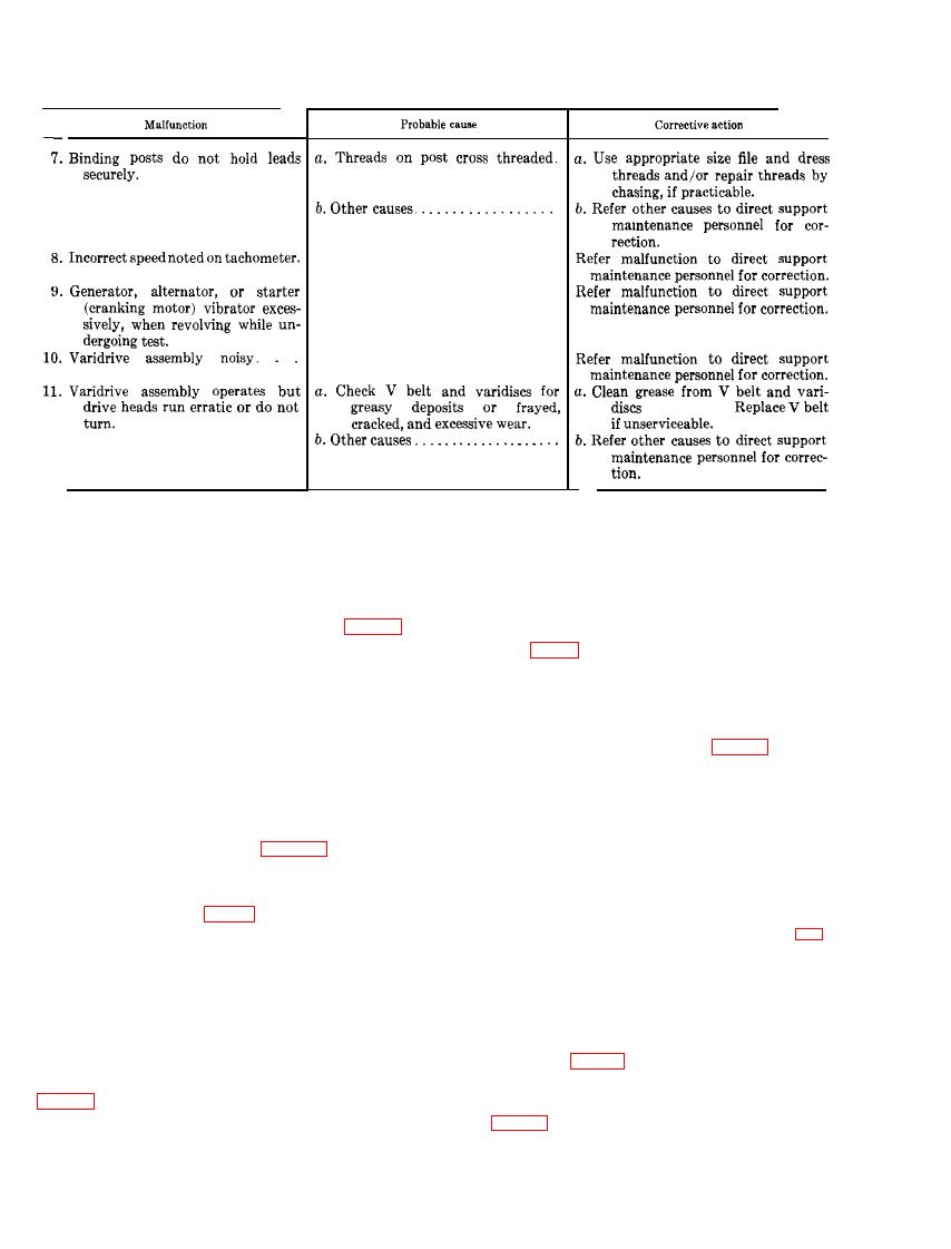
13.
Troubleshooting
-
Continued
(par.
146).
INPUT POWER SUPPLY FUSE GROUP
Section V.
b. Removal.
167. Description
The input power supply fuses consists of
(1) Open the drive reversing switch access
t h r e e 100-ampere 600-volt fuses (fig. 12)
door (high-voltage compartment)
mounted on a fuse block. The fuses have a knife
t y p e contact at each end and are pressed or
(2) Use a suitable type tool as a lever and
snapped into clip type connections on the fuse
pry the three 100-ampere 600-volt
block. The fuses provide short circuit protec-
fuses loose from the clips securing the
tion for the input power source circuit of the
fuses in the fuse block (fig. 12).
test stand.
c. Inspection.
168. Maintenance
(1) Inspect the fuses for damaged, cor-
a. General. Organizational maintenance is
roded, and burned condition.
a u t h o r i z e d to remove and replace the three
100-ampere 600-volt fuses (figs. 12 and 65).
(2) Check each fuse for continuity using a
W a r n i n g : Disconnect the external power
s u p p l y source, and place the on-off input
d. Installation. Place three serviceable 100-
power toggle switch (fig. 11) in the "OFF" posi-
ampere 600-volt fuses in the fuse block (figs.
tion, before any attempt is made to remove the
12 and 65).
three 100-ampere 600-volt fuses.
INDICATOR LAMP GROUP
Section VI.
169. Description
control panels (fig. 16) and are inclosed by a
The indicator lamps (30-A, 31, 34, and 45,
torpedo type lens. The three indicator lamps of
t h e battery circuit selector instrument panel
socket assembly built within the main and front
(41, fig. 16) are installed in a screw-in type

