
TM9-4935-481-14-1
C4
separate direct sets (SD) are available. The direct inputs override all synchronous inputs.
f.
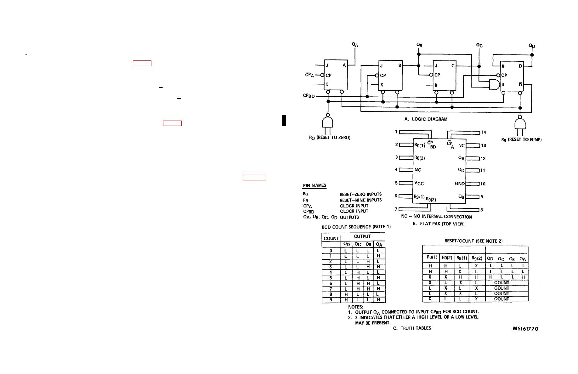
BCD Decade Counter.
(1) BCD decade counter. (MIS-18698/107-01) (fig. 3-21) This is a decade counter, which consists of four dual rank,
master slave flip-flops internally interconnected to provide a divide-by-two counter and a divide-by-five counter. Count inputs
are inhibited, and all outputs are returned to logical zero on a binary coded decimal (BC) count of 9 through gated direct reset
lines. The output from flip-flop A is not internally connected to the succeeding stages, therefore, the count may be separated
into these independent count modes: If a symmetrical divide-by-10 count is desired, the QD output must be externally
connected to the CPA input. The input count is then applied at the CPBD input and a divide-by-10 square wave is obtained at
output QA. For operation as a divide-by-two counter and a divide-by-five counter, no external interconnections are required.
Flip-flop A is used as a binary element for the divide-by-two function. The CPBD input is used to obtain binary divide-by-five
operation at the QB, QC and QD outputs. In this mode, the two counters operate independently; however, all four flip-flops
are reset simultaneously.
(2) BCD decade synchronous counter. (MIS-18698/120-01) (fig. 3-22)
(a) This is a high speed BCD fully synchronous decade counter with the clock pulse driving four master-slave
flip-flops in parallel through a clock buffer. During the LOW to HIGH transition of the clock, the master is inhibited from
further change. After the masters are locked out, data is transferred from the master to the slaves and reflected at the
outputs. When the clock is HIGH, the masters are inhibited and the master-slave data path remains established. During the
HIGH to LOW transition of the clock, the slave is inhibited from further change, followed by the enabling of the masters for
the acceptance of data from the counting logic.
(b) The start of the clock pulse driving this counter is hereby defined as HIGH-to-LOW transition. The end of the
clock pulse is defined as LOW-to-HIGH transition. That is, the clock pulse is a low-going pulse as shown in figure 3-23.
(c) The clock period is hereby defined as time from the end of one LOW-to- HIGH transition to the end of the
next LOW-to-HIGH transition. When all other conditions for counting are satisfied, the counter will respond [output(s) will
change state] to the LOW-to-HIGH transition (trailing edge) of the clock. The counter has
Figure 3-21. BCD decade counter
3-24

