
TM9-4935-481-14-1
C4
Table 3-10. DMS-D Maintenance Calibration-Continued
Table 3-10. DMS-D Maintenance Calibration-Continued
STEP
UNIT
PROCEDURE
CORRECTIVE ACTION
STEP
UNIT
PROCEDURE CORRECTIVE ACTION
463
OSC
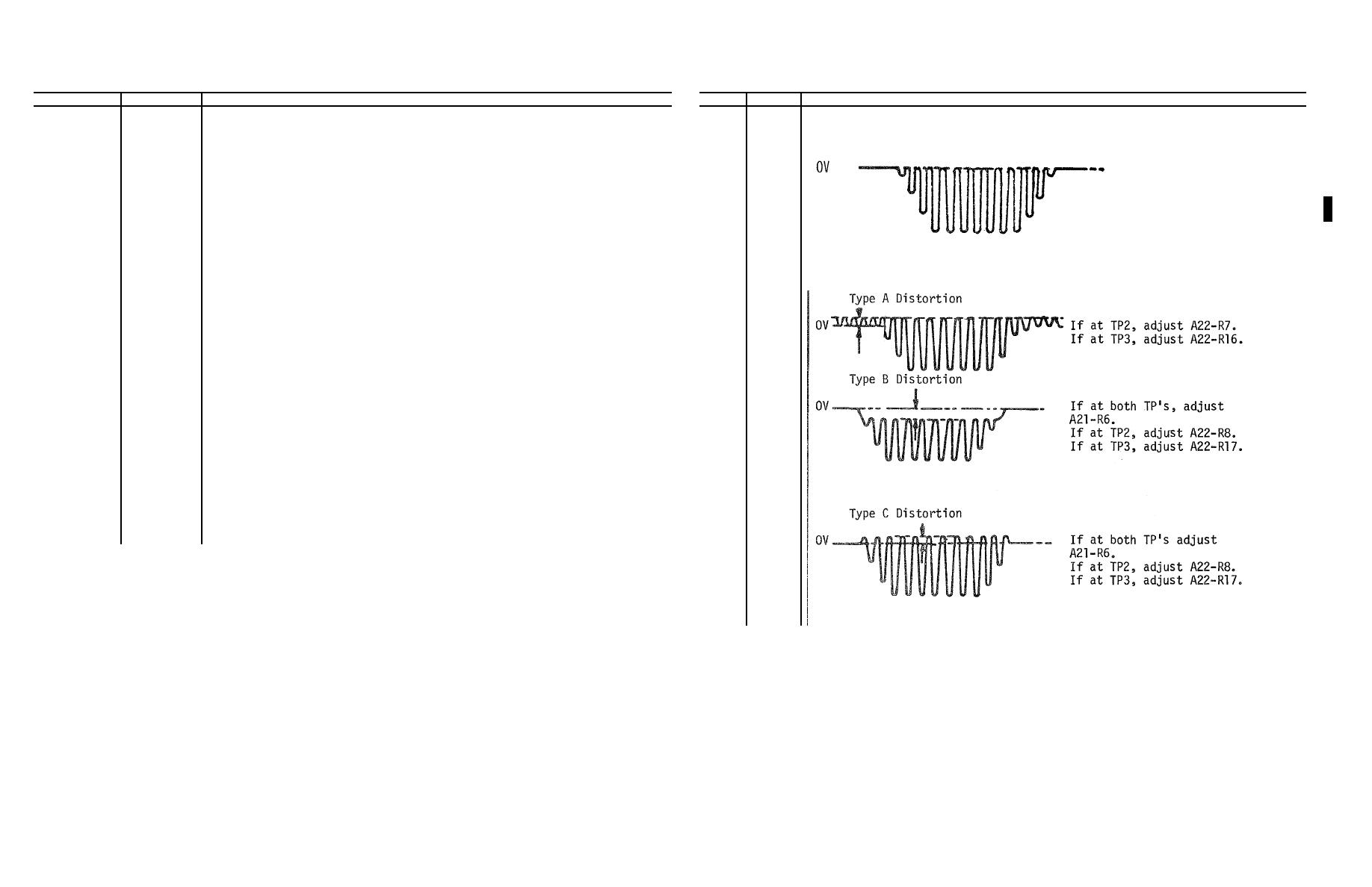
Adjust MAIN, TRIGGER LEVEL control until the following waveform
444
TKP
Adjust FREQ control to 8300 + 50 Hz.
is displayed and observe the upper peaks, identifying any
445
MCP
DMM INPUT switch to DMM INPUT
distortion present as per the waveforms shown following step
464.
446
Connect the DMM pos probe to A22-TP1 (BLK).
447
TKP
Adjust VERT (VOLTS) dial to 950.
448
TKP
Adjust HORIZ (VOLTS) dial to 950.
449
TKP
VERT(VOLTS) switch to PLUS.
450
TKP
HORIZ (VOLTS) switch to PLUS.
464
OSC
Remove the probe from A22-TP3, and connect it to A22-TP2 (BRN).
451
DMM
Adjust A22-R1 to 0.0000 + 0.0020 Vdc.
Again observe the upper peaks and identify any distortion pres-
ent. Make necessary adjustment as indicated within 10 mv,
452
Remove the probe from A22-TP1 (BLK).
adjusting type A and B distortion first, then type C and D.
453
TKP
HORIZ (VOLTS) switch to ZERO.
454
TKP
VERT (VOLTS) switch to ZERO.
455
OSC
TIME/DIV switch to 2 MSEC.
456
OSC
INT/EXT pushbutton to EXT.
457
OSC
MAIN AC/DC pushbutton to AC.
458
OSC
Channel A input COUPLING switch to DC.
459
OSC
Channel A input VOLT/DIV switch to .02.
460
OSC
Adjust A POSITION control until the trace is on the middle line
of the graticule.
461
OSC
Connect a coax cable between the ext. trig. input and pin 70 of
the adapter at J6.
462
OSC
Connect a 10215396 cable to the A INPUT and the white probe to
A22-TP3 (RED). Connect the BLK probe to J33 (GND).
3-74

