
TM9-4935-481-14-1
C3
Table 3-14. TTS Performance Test-Continued
Table 3-14. TTS (10219956) Performance Test
STEP UNIT
PROCEDURE
CORRECTIVE ACTION
STEP
UNIT
PROCEDURE
CORRECTIVE ACTION
NOTE
NOTE
After replacement of cards 1A7, 1A9, 2A1 or 3A1 the TTS maintenance calibration
The major units and panels will be identified by the initials as indicated below.
DMS-D
DMM
DIGITAL MULTIMETER
1
Prepare the DMS-D for testing per paragraph 2-6.
CT
COUNTER-TIMER
2
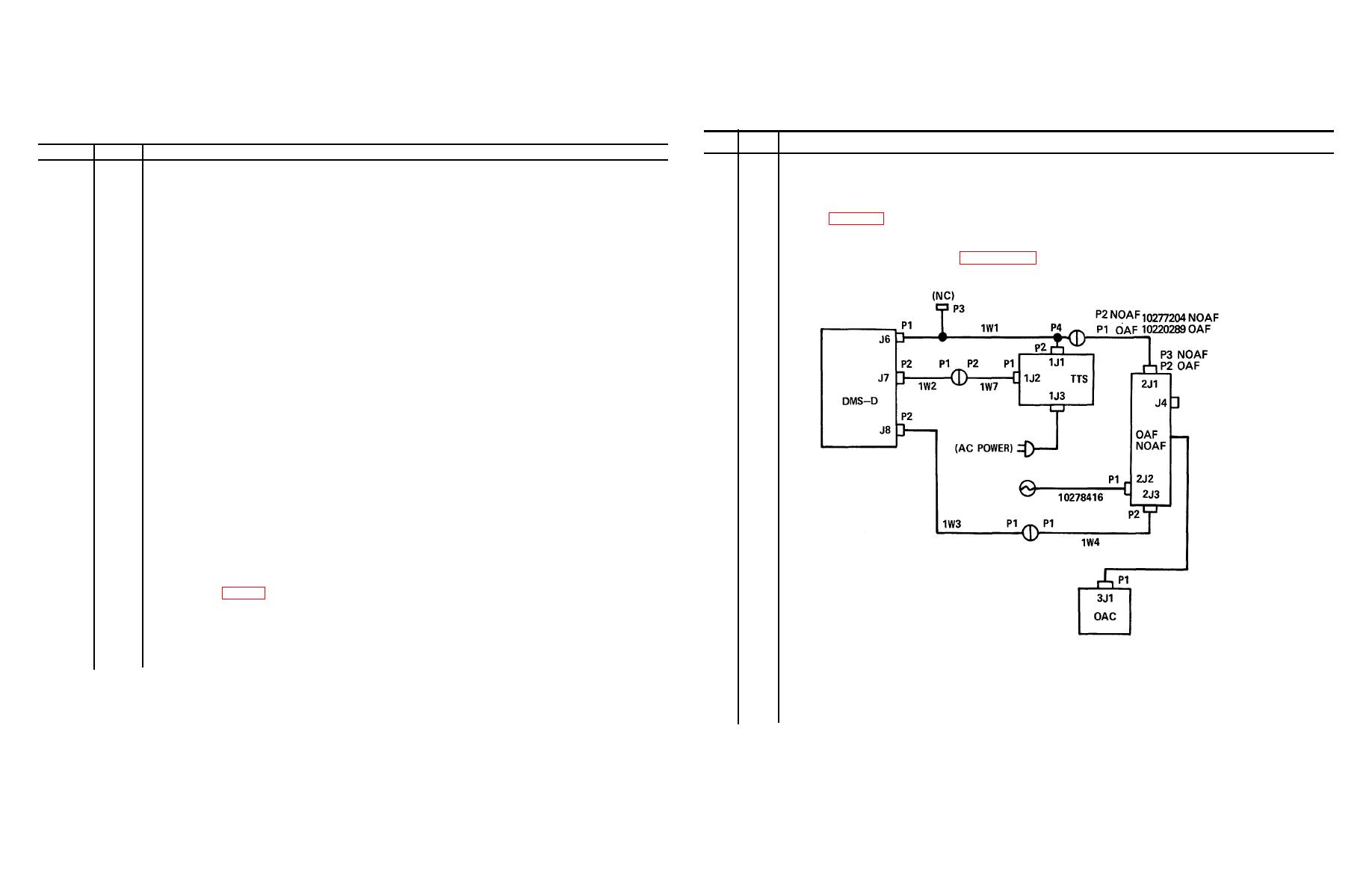
Prepare the TTS/TSG for testing per TM 9-4935-484-14, and connect the cables as depicted below.
PP
POWER panel
MCP
MONITOR/CONTROL panel
CIP
COUNTER INHIBIT(SEC) panel
PPE
PROG PERFORM EVAL panel
TPS
TRIGGER PULSE SIM panel
PD
PEAK DETECTOR panel
TP
TRAINER panel
RAD
RADIOMETER
OSC
OSCILLOSCOPE (AN/USM-338)
TTS
TRACKER TEST SET
OAF
OPTICAL ALIGNMENT FIXTURE
OAC
OPTICAL ALIGNMENT COLLIMATOR
TSG
TEST SET GROUP
NOAF
NIGHT OPTICAL ALIGNMENT FIXTURE
NOTE
Refer to fig. 3-36 for test point and potentiometer locations. For fault isolation where marked by
a,() see pages at the end of this table. Otherwise refer to schematic diagram and components
location in TM 9-4935-483-34.
.
3
TTS
POWER switch to OFF.
4
CIP
RUN/HOLD/OFF switch to RUN.
5
CIP
COUNTER INHIBIT(SEC) dial to 05.00.
3-217

