
C-2
TM 9-4935-481-14-2
mounting plate, right side up, with the holes aligning with the holes in the mounting plate. Secure with three screws (8).
(5)
Apply the two strips 0. 260 inch long horizontally between the two strips applied to each side and the latch
pin fixtures.
(8) Tighten the screw (9) until there is a very slight drag on the potentiometer shaft and turn the operating knob
ccw until the dial reads "000". Tighten screw (9) in this position. This insures that the potentiometer is against the ccw stop
(6) Apply the four remaining pieces vertically on either side of the two latch pin fixtures to form a complete seal
when the dial reads "000"
.
around the DMM.
(9) The axial position of the operating knob (6) will determine the depth of the mesh between the crown gear in
(7) Apply contact pressure and squeeze out excessive adhesive. Toulene or MEK may be used to wipe off
the knob and its associated pinion gear. The knob may therefore require slight adjustments in or out until the gears run
excessive adhesive.
freely.
(8) Allow to cure for 6 hours before handling.
(10) Install two screws (10) in the control knob.
f.
Replacement of CT.
c.
Installation of Inverter Assembly PS2 under Top of DMS-D Case.
(1)
If a new CT is to be installed, remove the unnecessary hardware (if applicable) as follows:
(1) Apply a thin film of silicone compound MIS-10350 to the unpainted surfaces
of the inverter assembly and the DMS-D case before assembly.
(a)
Hasp fasteners on sides.
(2) Install the inverter assembly, insuring the surfaces that touch each other are coated - providing thermal
(b)
Tilt stand.
conduction (heat sink action).
(c)
4 rubber feet.
d.
Installation of CT Gasket.
(d)
Eight screws in bottom and side plates and replace with screw NSN 530500-709-2010.
(1) Sand area where gasket touches metal lightly with #120 sandpaper. Clean metal surface with cleaning cloth
saturated with MEK and allow to air dry.
(2)
Install removed hardware on removed counter (if applicable) prior to disposition.
(2) Apply adhesive MIS-18631, TY 1 to metal and new CT gasket and install, applying contact pressure and
g.
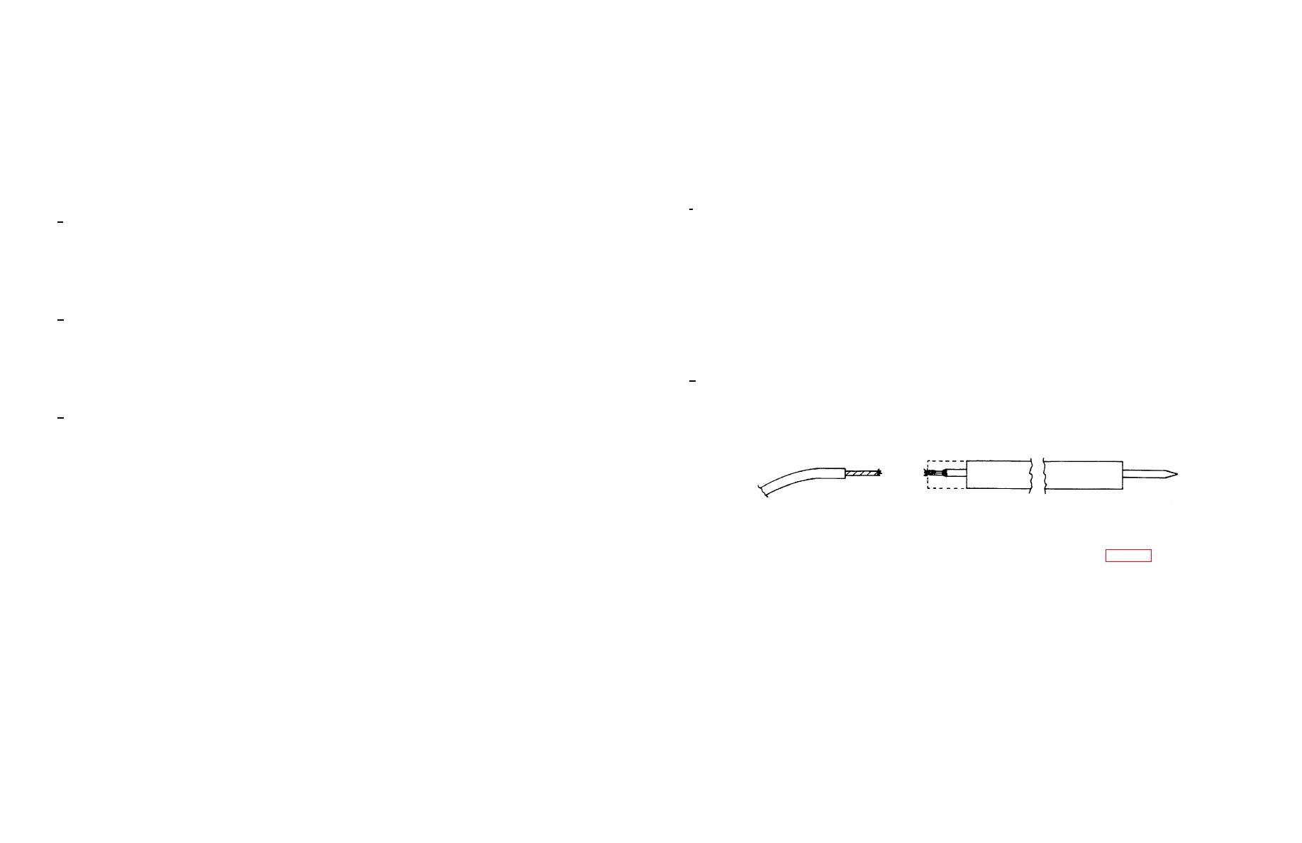
Repair of DMM Probes on Cable 1W14. If the test lead wire separates from the test prods, perform the following
forcing out excess adhesive. Remove excess adhesive with MEK and allow to cure 6 hours before handling.
procedure:
e.
Installation of DEPl Gaskets.
(1) Using the PACE mechanical drive, chuck assembly, and saw blade (PACE #1112-0061) cut away
approximately 5/8 inch of test prod as shown.
(1) The gasket surrounding the DMM will be fabricated from conductive gasket material 0.062" thick by 0.156"
wide (MIS-11284-11) cut to the following lengths:
2 pieces 0.260"
(10275071-1)
4 pieces 0.375"
(10275071-2)
2 pieces 4.750"
(10275071-3)
1 piece 7.140"
(10275071-4)
1 piece 9.100"
(10275071-5)
(2)
Strip 1/4 inch of insulation from the remaining test lead.
(2) Carefully sand the surfaces of the DMS-D case to be bonded with #120 grit sandpaper. Wipe clean with
(3) Cut a 2 inch length of each of the following sizes of insulation sleeving (see table 5-1) and slide onto the test
trichlorethane and allow to dry at least 5 minutes.
lead: MIL-I-023053/5-. 093, -.250, and -.375.
(3) Apply adhesive (MPD 9148, four parts base to one part hardener) to the case, and to one side of the gasket
(4) Lap solder the test lead to the exposed metal center of the test prod, and shrink each of the three 3 pieces of
strips. (This is a conductive adhesive.)
insulation sleeving in turn over the exposed joint, as shown.
(4) Apply the longest strip centered across the top, the two strips 4.750 inches long down each side, and the
piece 7. 140 inches long centered across the bottom, between the two latch pin fixtures.
5-10

