
TM 9-2330-211-14&P
1-9.
EQUIPMENT DATA (Con't)
Landing Gear:
Type ..........................................................................................................................
Vertical Screw
Manufacturer ..............................................................................................................
Austin
Model .........................................................................................................................
J3202
Electrical System ............................................................................................................
24 Volts, 12 Pin Receptacle
Section III. PRINCIPLES OF OPERATION
Page
Page
Airbrake System ...............................................
Lighting System ................................................
1-10.
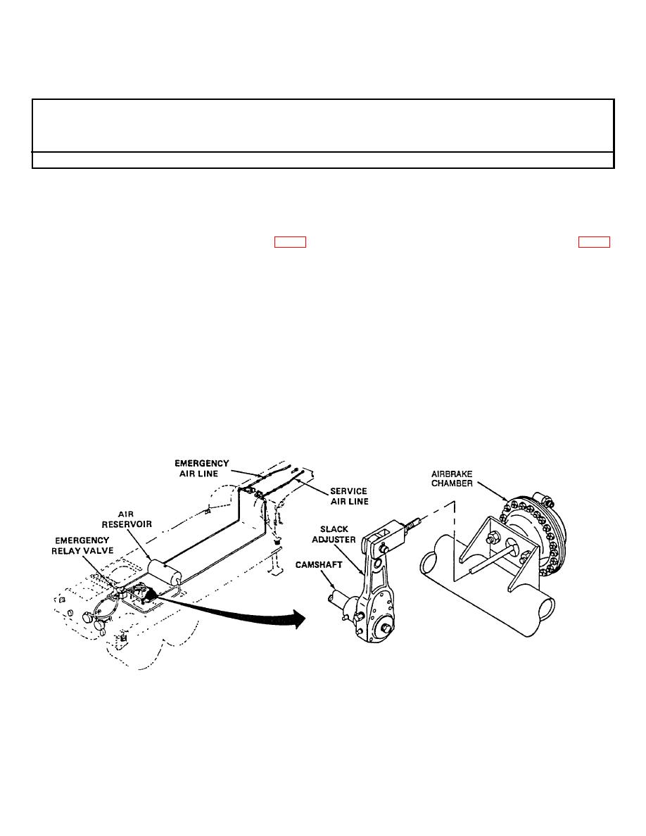
AIRBRAKE SYSTEM
Tractor air supply pressure should not be less than 50 psi (345 kPa) for proper brake application. When the brake air
hose is connected between the tractor and the semitrailer, air flows through the emergency air line and emergency relay
valve. Air pressure is built up to equal the pressure in the system of the tractor.
When pressure Is applied to the brake pedal of the tractor, air pressure Is directed through the service air line to the
emergency relay valve. This valve releases reservoir air to the airbrake chambers. Air pressure behind the airbrake
chamber diaphragms moves the slack adjusters. The slack adjusters operate the camshafts, which forces the
brakeshoes against the drum. Brakeshoe and drum friction slows, stops, and/or holds the semitrailer until the brake
pedal/lever Is released, allowing applied air to vent.
TA506785
1-6
