
TM 9-2590-506-13&P
1-6.
LOCATION AND DESCRIPTION OF MAJOR
COMPONENTS (Continued).
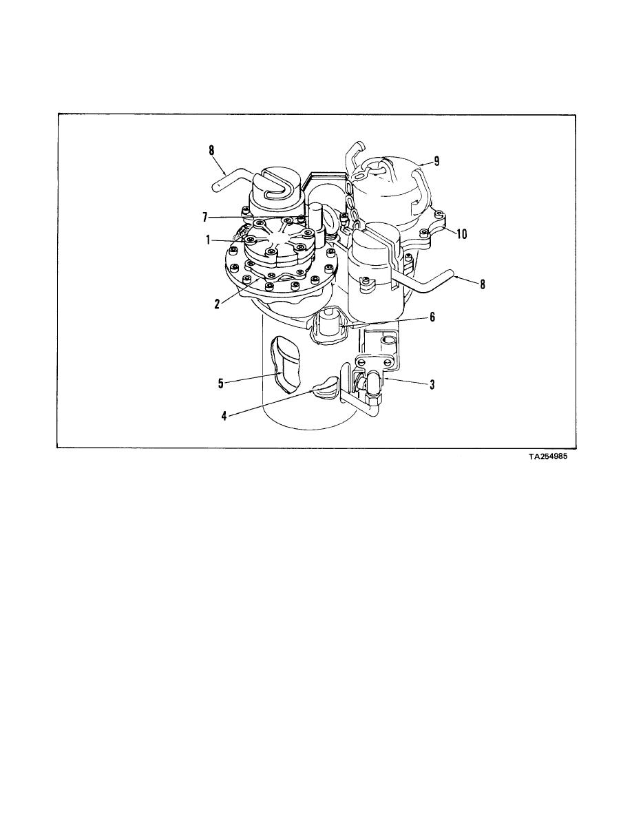
(4) PILOT ASSEMBLY (4). Pressure from the
(7) DRAIN BUTTON (7). Depressed after tank
jet sensor pushes the pilot off of the seat
filling to drain fuel from converter assembly
allowing the internal valve to open. With the
by opening piston.
internal valve open the tank will fill. When
the tank is full the jet sensor pressure will
(8) LATCH COVER LEVERS (8).
Engages
shut down closing the internal valve.
latches with tank opening to secure
converter assembly during fueling operation.
(5) INTERNAL VALVE (5). Contains a piston
Allows converter assembly to unseat from
which opens to allow the tank to fill. The
tank when internal pressure exceeds 3.5
pilot assembly opens the piston.
psig to prevent tank rupture.
(6) LEVEL CONTROL SWITCH (6). Controls
(9) DUST COVER ASSEMBLY (9) AND VENT
fuel level in tank. As fuel rises, the float
(10). The dust cover assembly covers the
(with magnet) opens the reed switch
vent opening when the converter assembly
shutting down fuel delivery.
is not in use. The vent provides a means of
attaching the vent line to remove vapors
during the filling operation.
1-3

