TM 1-4920-441-13&P
0021 00
NOTE
Once panel boards are removed, all further procedures are identical for both
models.
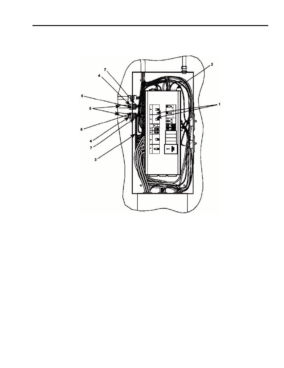
5. With circuit breaker box door and panel cover removed, disconnect wires from 30A, 240V circuit breakers (1),
neutral bar (2), and ground bar (3).
6. Loosen compression nut (4) on outside of circuit breaker box that is securing ECU power cable (5) in box
connector (6).
7. Pull ECU power cable through and out of box connector (6).
8. Remove box connector lock nut (7) from inside circuit breaker box wall.
9. Remove damaged box connector (6) and discard.
Install
1. Insert new box connector (6) into hole in side of circuit breaker panel, place compression nut (4) on box
connector (6) and tighten.
2. Push cable through box connector (6) and locate at original position.
3. Tighten compression nut (4).
4. Connect wires to 30A, 240V circuit breaker (1).
5. Replace panel board and cover.
6. Move main circuit breaker to the ON position.
0021 00-7

