TM 55-1925-286-13&P
0004 00
AIR COMPRESSORS AND DISCHARGE MANIFOLDS CONTROLS AND INDICATORS
3
4
2
1
5
7
6
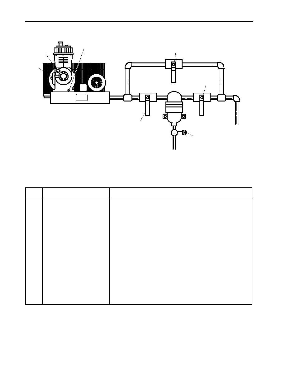
Figure 3. Air Compressors and Discharge Manifolds
Table 3. Air Compressors and Discharge Manifolds (refer to figure 3)
Key
Control/Indicator
Function
1
Dipstick
The dipstick permits the operator to check the lube oil level in the
air compressor crankcase.
2
Oil Pressure Gauge
This gauge indicates the lube oil pressure for the air compressor.
3
Drain Fitting
This drain permits draining of the lube oil from the crankcase.
4
CA-89 and CA-90
OPEN this valve to bypass the air dryer.
COV-COMPR DISCH
5
CA-87 and CA-88
When CLOSED, these valves secure the discharge side of the
COV-COMPR DISCH
air dryer.
6
CA-93 and CA-94
OPEN these valves to drain the air dryer. The drain sends all
MOISTURE SEP DR
trapped moisture to the bilge when opened.
7
CA-1 and CA-2
CLOSE these valves to cut off the air dryer.
COV-COMPR DISCH
0004 00-4

