TM 9-2330-246-14
Section Il. MANUFACTURING INSTRUCTIONS ( C o n ' t )
1. Assembly Instructions.
a. Binding. Cables shall be bound together with one-half overlapping turns of electrical
insulation tape (Item 28, Appendix E).
NOTE
Do not distort skirts of pin contacts (MS27148) when crimping to conductors.
b. Crimping. Crimp pin contacts (ferrules), terminals, and splicing connectors to cables
(conductors and/or insulation).
terminal assemblies in accordance with TM 9-237.
d. splicing.
(1) Spliced conductors must be adequately insulated and the insulation must be sealed to
each cable's insulation,
(2) Vulcanize splices using solid rubber sheet (Item 21, Appendix E). Thickness of rubber over
exposed conductors will be 1/8-5/32 in. (3.18 to 3.97 mm) and is to overlap adjacent
insulation for a distance of at least 3/16 in. (4.76 mm) and a minimum thickness of 1/32 in.
(0.79 mm).
e. Plugging. Plug all spare grommet holes with rod of diameter and length as required.
2. Circuit 490 and associated parts used with part number 11646259 only.
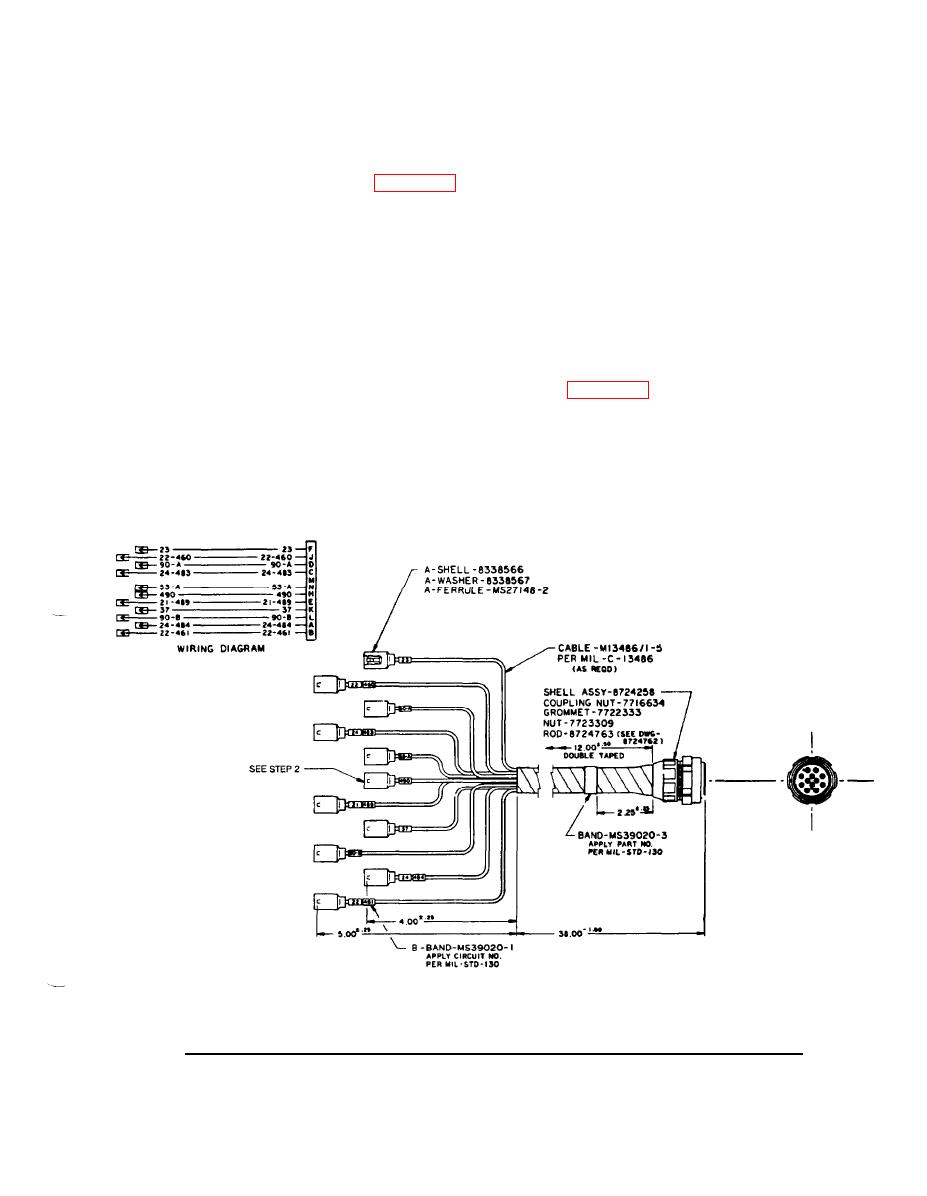
Figure F-5. Interconnecting Wiring Harness.
TA700399
F-7

