TM 9-2330-381-14
12.
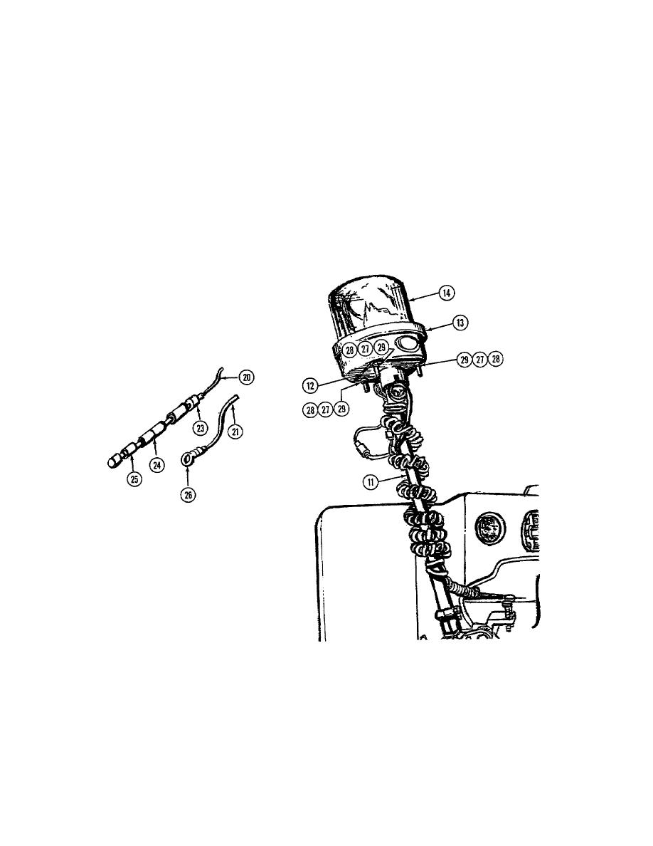
Using electrical repair kit, measure and cut both red (+) lead (20) and green (-) lead (211 4.0 inches (10 cm) from
bottom of warning light bottom over (16).
13.
Using electrical repair kit, strip ends of both red (+) lead (20) and green (-) lead (21) approximately 0.5 inches (1.7
cm).
14.
Install cable nipple (23) over red (+) lead (20). Push cable nipple (23) upward against bottom of warning light
bottom cover(16). Install insulator (24) onto red (+) lead (20). Push insulator (24) upward approximately 3.0
inches (7.6 cm) from end of red (+) lead (20). Install terminal assembly (25) onto stripped end of red (+) lead (20).
Crimp terminal assembly (25) securely onto red (+) lead (20).
15.
Install circular ring terminal lug (26) onto stripped end of green (-) lead (21). Crimp circular ring terminal lug
securely onto green (-) lead (21).
16.
Align mounting holes in warning light bottom cover (16) with mounting holes in plate (12) and install three screws
(27), lockwashers (28) and (29).
4-541


