TM 9-2330-384-14&P
1-13. BRAKE SYSTEM (Con't).
FUNCTION
NAME
KEY
4
Front and Rear Air
Store compressed air under carefully controlled pressures until
Reservoirs
needed for use.
5
Draincock Cable
Connected to front and rear air reservoir draincocks. When pulled,
allows drainage of moisture from air system.
6
Brake Chambers
Consist of two separate chambers:
Receives a constant flow of air pressure to maintain spring
Rear Chamber
deactivated for normal operation. With loss of air pressure during
uncoupling, parking operations, or in an emergency, spring is
activated and causes a mechanical parking/emergency brake
operation.
Receives air pressure when service brakes in tractor are
Front Chamber
applied. Air pressure is converted to mechanical energy and sent
to slack adjusters by way of brake chamber pushrod, and from
there along camshafts to brake shoe assemblies.
FUNCTION
KEY
NAME
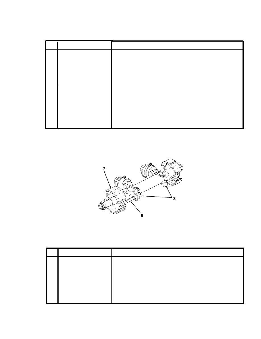
7
Brake Shoe Assemblies
Attached to axle at spider. Actuated by S-cam at end of camshaft
to apply pressure for slowing or stopping drum rotation.
8
Slack Adjusters
Part of mechanical linkage. Function as an adjustable lever. Provide
a quick and easy method of adjusting brakes to compensate for
normal brake shoe lining wear. Are automatically self-adjusting
under normal conditions.
9 Camshafts
Connected to slack adjusters. S-cam at end of camshaft serves to
actuate brake shoe assemblies.
1-29


