

Custom Search
|
|

|
||
 TM 9-2330-394-13&P
ELECTRICAL SYSTEM TROUBLESHOOTING - Continued
0036 00
ELECTRICAL SYSTEM - Continued
Table 1. Electrical System Troubleshooting Procedures - Continued
MALFUNCTION
TEST OR INSPECTION
CORRECTIVE ACTION
2.
ONE OR MORE REAR
6.
Connect negative (-) probe
MARKER LIGHTS DO NOT
of digital multimeter to
ILLUMINATE - CONTINUED
terminal lug TL261.
7.
Note reading on digital
multimeter.
8.
If continuity is not present,
repair wire (WP 0043 00) or
replace electrical cable
assembly (WP 0051 00).
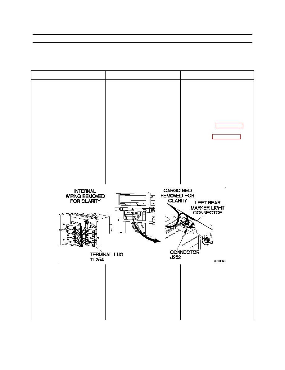
6.
Check for continuity between
1. Set digital multimeter to
terminal lug TL254 and
ohms.
connector J252.
2.
Connect positive (+) probe
of digital multimeter to
terminal lug TL254.
3.
Disconnect connector J252
from left rear marker light
connector.
4.
Connect negative (-) probe
of digital multimeter to
connector J252.
5.
Note reading on digital
multimeter.
0036 00-10
|
||
|
||


