

Custom Search
|
|

|
||
 TM 9-2330-394-13&P
ELECTRICAL SYSTEM TROUBLESHOOTING - Continued
0036 00
ELECTRICAL SYSTEM - Continued
Table 1. Electrical System Troubleshooting Procedures - Continued
MALFUNCTION
TEST OR INSPECTION
CORRECTIVE ACTION
4.
LEFT FRONT MARKER
11. Install base on trailer with
LIGHT DOES NOT
four washers and screws.
ILLUMINATE - CONTINUED
12. Install lamp in socket.
13. Install lens on base with two
screws.
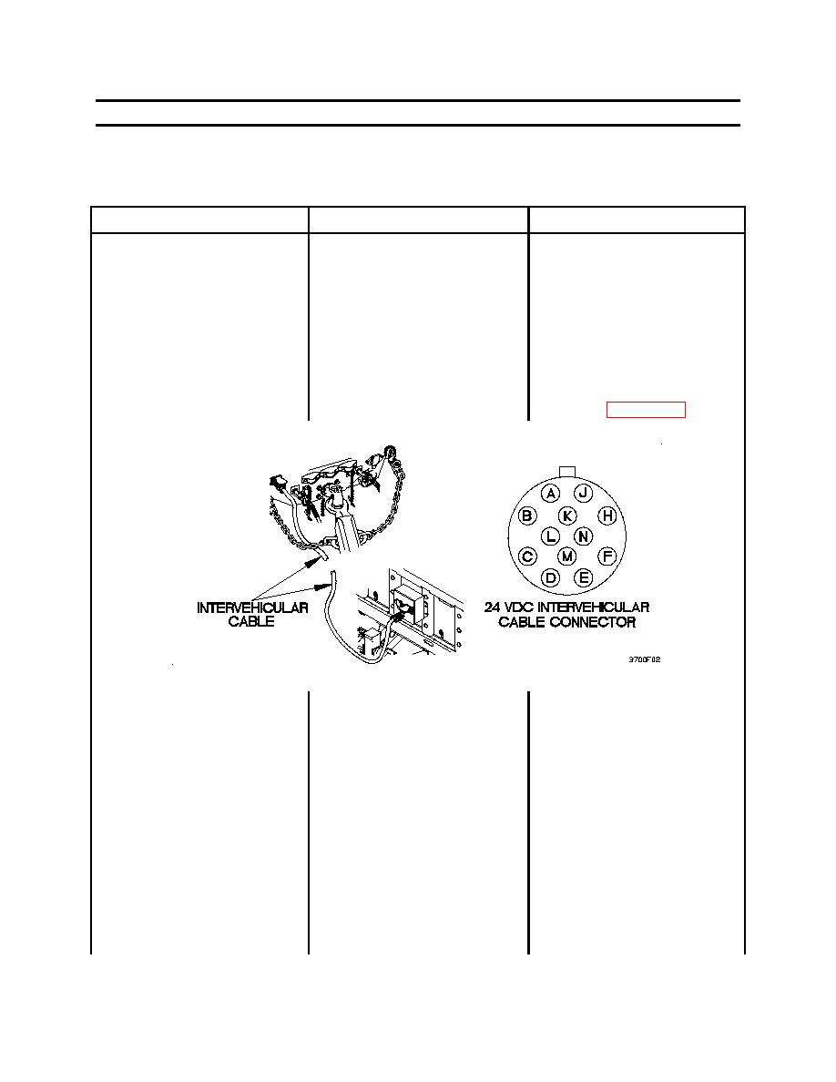
5.
BOTH FRONT MARKER
1.
Check for 18-24 vdc at
1.
Disconnect 24 vdc
LIGHTS DO NOT
intervehicular cable
intervehicular cable from
ILLUMINATE
connector pin E.
trailer (WP 0012 00).
2.
Set digital multimeter to
ohms.
3.
Connect positive (+) probe
of digital multimeter to 24
vdc intervehicular cable
connector pin E.
4.
connect negative (-) probe
of digital multimeter to a
known good ground.
5.
Position towing vehicle main
light switch to SER DRIVE
6.
Note reading on digital
multimeter.
0036 00-32
|
||
|
||


