

Custom Search
|
|

|
||
 TM 9-2330-394-13&P
ELECTRICAL SYSTEM TROUBLESHOOTING - Continued
0036 00
ELECTRICAL SYSTEM - Continued
Table 1. Electrical System Troubleshooting Procedures - Continued
MALFUNCTION
TEST OR INSPECTION
CORRECTIVE ACTION
9.
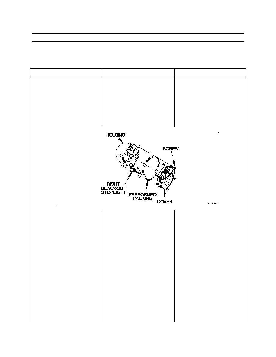
RIGHT BLACKOUT
6.
If left blackout stoplight
STOPLIGHT DOES NOT
does not illuminate, go to
ILLUMINATE - CONTINUED
step 5 of this malfunction.
2.
Check to see if 18-26 vdc is
1.
Loosen six screws and
present at right blackout
remove cover and
stoplight lamp socket center
preformed packing from
contact.
housing. Discard preformed
packing.
2.
Remove blackout stoplight
from socket.
3.
Set digital multimeter to
volts dc.
4.
Connect positive (+) probe
of digital multimeter to
blackout stoplight lamp
socket center contact.
5.
Connect negative (-) probe
of digital multimeter to a
known good ground.
6.
Position towing vehicle main
light switch to BO DRIVE
and note reading on digital
multimeter.
7.
Position towing vehicle main
light switch to OFF.
0036 00-59
|
||
|
||


