

Custom Search
|
|
|
|
||

|
||
 TM 9-2330-394-13&P
BRAKE SYSTEM TROUBLESHOOTING - Continued
0037 00
BRAKE SYSTEM - Continued
Table 1. Brake System Troubleshooting Procedures - Continued.
MALFUNCTION
TEST OR INSPECTION
CORRECTIVE ACTION
3.
Connect negative (-) probe
14. ANTI-LOCK BRAKING
of digital multimeter to a
SYSTEM (ABS) DIAGNOSTIC
known good ground and
TOOL BLINKS 10 TIMES IN
note reading on digital
SERIES: ABS MODULATOR
multimeter.
VALVE FAULT - CONTINUED
4.
If continuity is not present,
go to step 8 of malfunction.
5.
If continuity is present,
replace ABS ECU (WP 0065
3.
Check to see if continuity is
1.
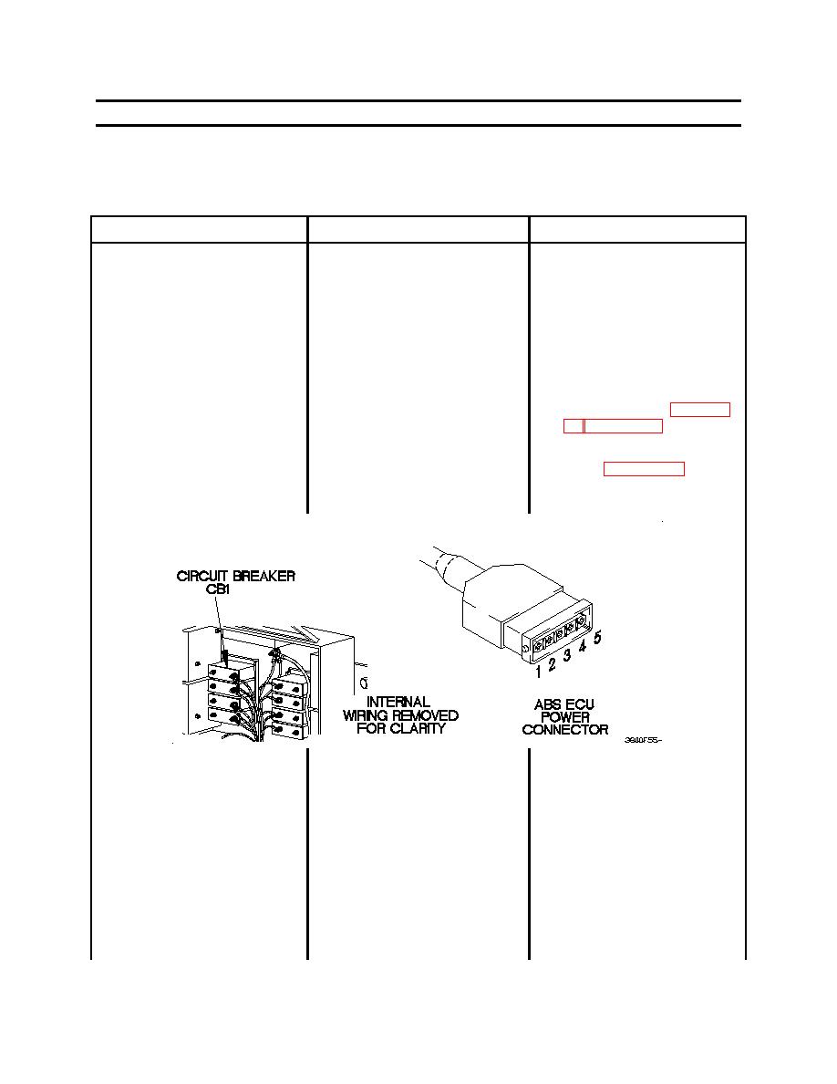
Open voltage converter box
present between ABS POWER
cover (WP 0053 00).
connector and circuit breaker
CB1.
2.
Set digital multimeter to
ohms.
3.
Connect positive (+) probe
of digital multimeter to
POWER connector pin 1.
4.
Connect negative (-) probe
of digital multimeter to right
side terminal of circuit
breaker CB1 and note
reading on digital
multimeter.
0037 00-61
|
||
|
||


