
TM 9-2330-398-10
2-3. VALVES, PIPING, AND DISPENSING COMPONENTS.
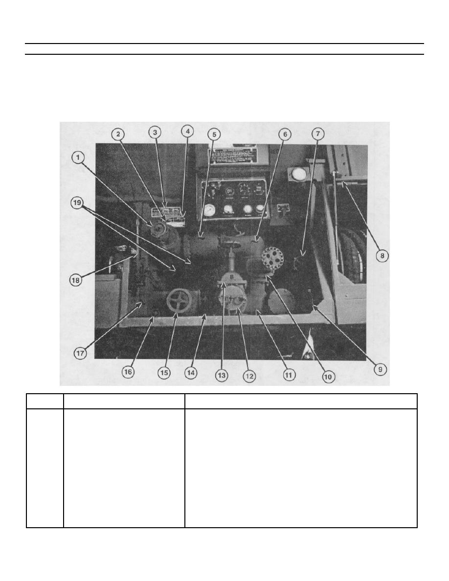
The operator/crew should become thoroughly familiar with the location of valves, piping, and dispensing components, and
with the piping schematic mounted on the storage box cover before beginning any fuel-servicing or fuel-dispensing
operation.
Piping Control Assembly. This assembly contains a four-inch pilot-operated control valve, plus the components
listed in the table that follows.
KEY
COMPONENT
DESCRIPTION
1
Bottom Loading Adapter (D-1)
Allows tanker to be closed-circuit loaded from the
bottom
2
Valve E
Located next to precheck valve (D). Provides load/
unload selection.
3
Fuel-Dispensing Instruction Plate
Provides engine rpm and pump gpm requirements
during fuel-dispensing operations
4
Valve D, Precheck
Provides a way to check shut-off float for proper
functioning.
2-4
