TM 9-2350-275-BD
COMMUNICATIONS SYSTEM
Procedural Steps (Cont):
NOTE:
Cut as close to the handset and microphone as possible so a
long cord and the plug will be intact.
c. Strip 6 inches of outer insulation off the cut end of each of the cords, being
careful not to cut the inner wires.
d. Strip 1/2 inch of insulation off the end of each of the exposed wires.
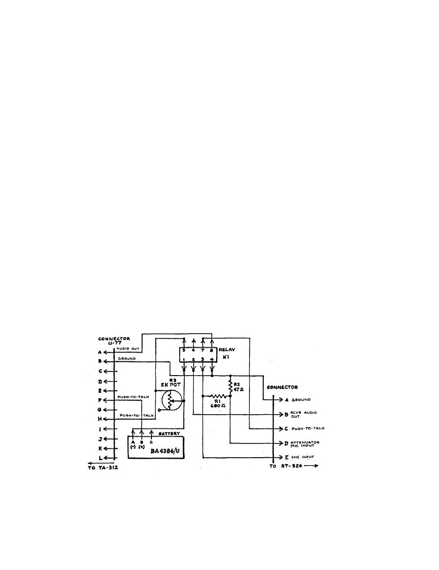
e . Use the multimeter or continuity tester to match the wires with the pins in'
the plug using referenced letters.
f.
Solder the two resistors.
Solder the wires to points referenced.
g.
h. Solder the remaining wires using the 18-24 gauge wire.
NOTE
When connecting the wires to the battery plug, ensure they are connected as
shown.
D, E, G, I, K, J, and L on the U-77 connectors are not used.
11-48

