
TM 9-2590-209-14&P
f. Remove hoist and rope from power takeoff
i.
Fill hydraulic system (fig 3-1). Check for leaks.
assembly.
j. Install transmission shroud, and close rear grille
g. Connect electrical lead to magnetic clutch (view
doors. See TM 9-2350-215-20 (M60, M60A1), TM 9-
A).
2350-257-20-1 (M60A1 RISE), or TM 9-2350-253-20-1
(M60A3).
h. Connect two hydraulic hose assemblies to
hydraulic pump assembly, and secure with four flanges,
two packings, eight screws, and lockwashers (view A).
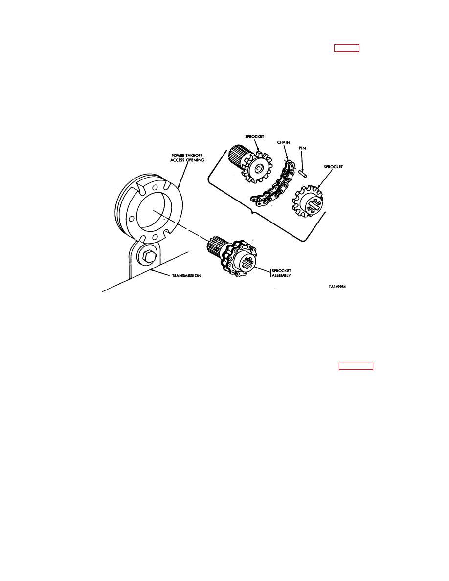
Figure 4-22. Disassembly or assembly of power takeoff sprocket assembly.
Section XX. MAINTENANCE OF BLADE CONTROL LEVER AND LINKAGE
a. Removal
4-86. Description. The blade control lever and linkage
(1) Drop escape hatch.
mechanically operates the manifold control valve. The
(2) Remove nut (1, fig 4-23) securing rod
blade control lever is located in the driver's compartment.
assembly (2) to bottom of control lever (23).
The linkage passes through the hull floor and extends
under the vehicle to the manifold.
4-87. Blade Control Linkage
4-49
