TM 9-2590-506-13&P
5-21. CONVERTER
ASSEMBLY
TESTING
INSTRUCTIONS (Continued)
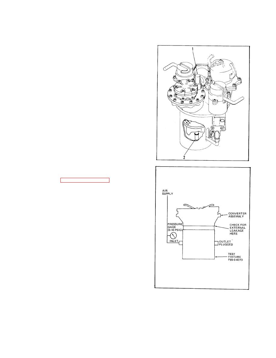
a. Checkout.
(1) Step on drain button (1) and observe that
shaft (2) of internal valve moves down as
the drain button is depressed.
(2) The shaft (2) shall return to its original
position after the drain button (1) is
released.
b. Testing.
(1) Install converter assembly in test fixture
(item 2, Appendix B, Section III) and place
latches in the LOCK position.
(2) Check that latches securely lock converter
assembly to test fixture.
(3) Apply 2.75 psig air pressure to inlet port
with outlet port plugged.
(4) Pressure shall not drop below 2.25 psig at
the end of a three minute period.
(5) Slowly increase air pressure at inlet port
with outlet port plugged.
(6) Converter assembly shall relieve at
pressure below 3.5 psig, as evidenced by
air leaking between converter assembly
and test fixture.
(7) Reduce air pressure to zero.
(8) Place latches in UNLOCK position and
remove converter assembly from test
fixture.
TA255052
5-44


