TM 9-4120-360-14
MALFUNCTION
TEST OR INSPECTION
CORRECTIVE ACTION
Make sure that condenser intake screen is not clogged or obstructed.
step 4.
Clean intake screen.
Remove evaporator intake grille, remove air filter and inspect for dirt or clogging of any kind.
Step 5.
Clean filter.
Inspect condenser coil for dirt or obstruction.
Step 6.
Clean coil with vacuum cleaner and brush attachment, or use 30 psi compressed air from
inside of coil to blow out dirt, keeping air nozzle at least eight inches from coil.
Check sight glass liquid indicator for bubbles. If bubbles exist check system for leaks.
Step 7.
Repair leaks, and recharge system.
Feel drier-strainer (dehydrator) to see whether it is cold to the touch, or is frosted or sweating. Cold discharge
Step 8.
indicates obstruction.
Discharge system over a period of 5-6 hours to prevent oil being blown out of system, then replace
drier-strainer.
Check inlet and discharge sides of solenoid valves for temperature difference. Abnormally cold discharge
Step 9.
indicates leakage or obstruction.
Repair or replace faulty solenoid valve.
Check evaporator coil for over-all temperature. If part of coil is relatively warm, and evaporator refrigerant
Step 10.
inlet is sweaty or frosty, expansion valve may be damaged or obstructed.
Replace faulty expansion valve.
3. FAN MOTOR DOES NOT OPERATE
Make sure that power cable is properly connected and that 3-phase power is supplied.
Step 1.
Connect cable.
Disconnect power from the air conditioner before doing maintenance work on the electrical
system. The voltage used can be lethal.
Check connectors P3 and P9 for proper tightness.
Step 2.
Tighten as necessary and retry starting.
Check continuity of fuses XF1 and XF2.
Step 3.
Replace bad fuses.
Remove lower panel, junction box cover, and control panel. Tag wires to mode selector switch for identification,
Step 4.
and disconnect wires from switch. Using an ohmmeter or continuity tester, check continuity in each position in
accordance with the following switch-position tabulation.
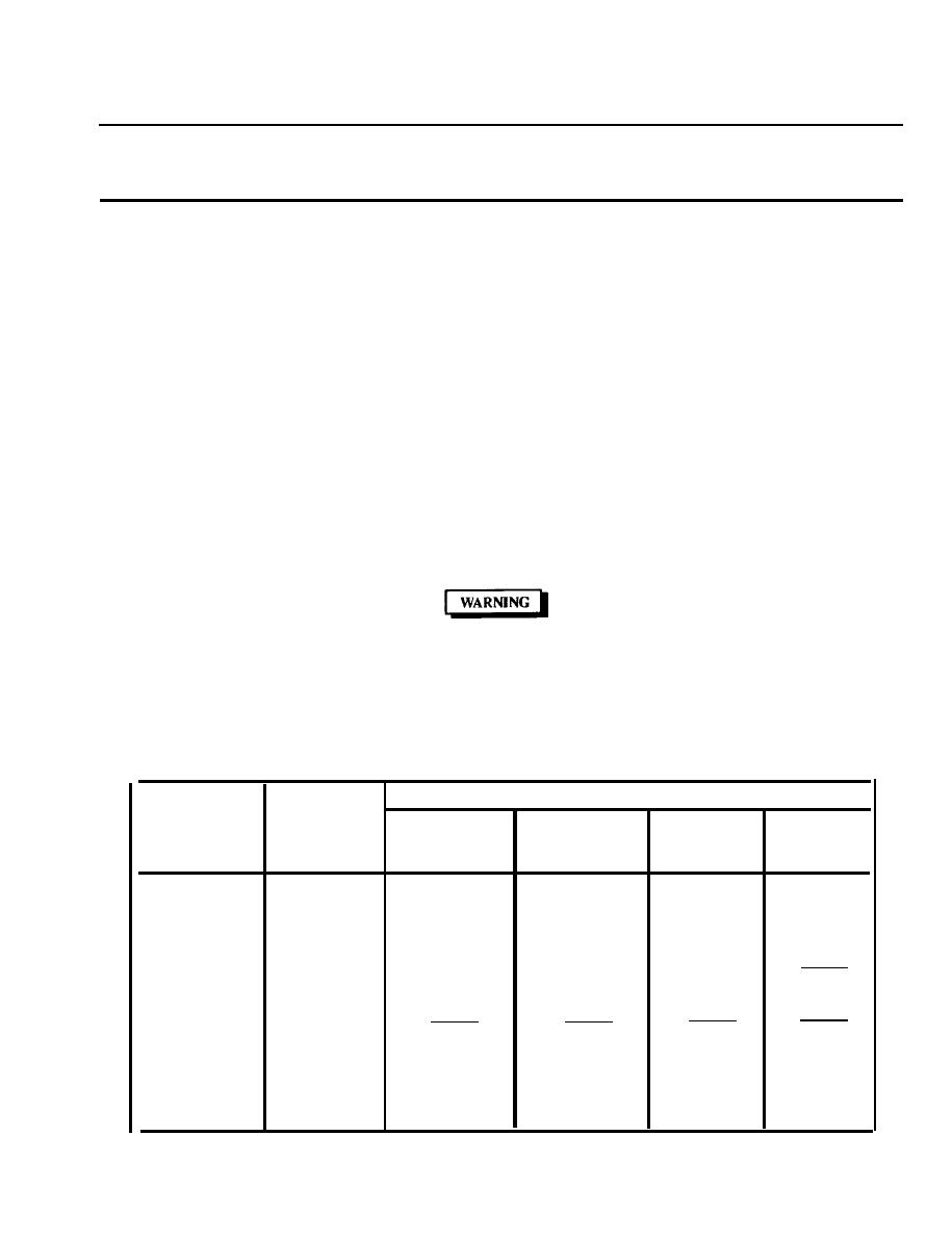
SWITCH WAFERS AND TERMINALS CONNECTED
SELECTOR
SWITCH
SWITCH
- S1 -
FUNCTION
S1C
S1D
S1B
S1A
POSITION
41 AND 4C
31 AND 3C
12 AND 1A
21 AND 2C
HEAT
1
42 AND 4A
32 AND 3A
22 AND 2B
(HIGH)
31 AND 3C
21 AND 2C
12 AND 1A
HEAT
2
22 AND 2B
(LOW)
OFF
3
21 AND 2C
4
VENT
31 AND 3C
22 AND 2B
41 AND 4D
31 AND 3C
21 AND 2C
12 AND 1B
5
COOL
42 AND 4B
22 AND 2B
32 AND 3B
11 AND 1D
4-9

