
b. Remove the panel mounting nuts from the two-speed fan switch and mode selector switch
c. Remove four screws and self-locking nuts that secure the back panel to the housing. Carefully separate the
panel from the housing.
d. Tag and remove wires from the two-speed switch.
e. Remove the four screws and self-locking nuts that secure the mounting flanges of the temperature control
thermostat to the rear cover. Press the capillary tube and grommet out of the notch in the rear cover to separate the
temperature control thermostat from the control panel assembly.
f. Remove four screws and self-locking nuts from the wiring harness receptacle, and remove the wiring
harness from the control panel assembly.
5.4. Inspect/Test
Inspect non-functional parts of the control panel assembly for damage. Replace damaged parts. Test operating
components as follows, using an ohmmeter, multi-meter or other continuity tester.
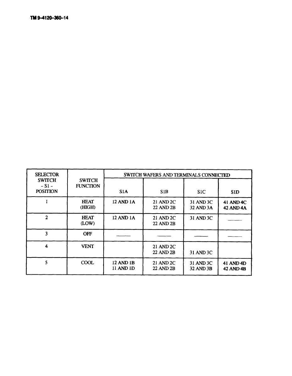
a. Check continuity of the mode selector switch in all positions, in accordance with the following Table:
b. Attach the continuity test leads to the red and yellow contacts of the temperature control thermostat, and place
the sensor bulb in a container of warm water (85 - 100 F or 30 - 40C), Check the continuity of the thermostat
throughout the DECREASE range, Continuity should be indicated.
c. Attach the continuity test leads to the red and blue contacts of the temperature control thermostat, and place
the sensor bulb in a container of cold water (40 - 65F or 50 - 18C). Check the continuity of the thermostat throughout
the INCREASE range. Continuity should be indicated.
d. Check cotinuity of the two-speed fan switch in both positions. Continuity should be indicated in the ON
position, but not in the OFF position.
e. Check the continuity of each pin and attached wire in the wiring harness. Continuity should be indicated.
Check from each pin to the plug or shell, Continuity should not be indicated.
f. If any component or part does not meet continuity requirements. replace it.
5-2
