
TM9-4120-400-14
RELAY K4. - continued
4-32.
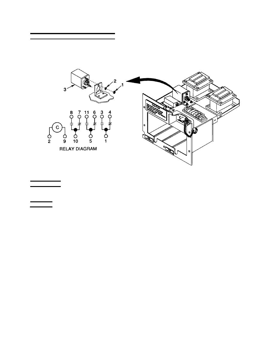
Figure 4-27. Relay K4
INSPECTION
Check relay for general condition, evidence of overheating, and loose, broken, or missing terminals.
TESTING
1. Apply +28VDC to terminal TB1-6 and -28VDC to terminal TB1-4.
NOTE
Terminals 10 and 8 are not used in single phase units.
2. Check continuity across terminals 1 and 3, 5 and 11, and 10 and 8.
3. Read Multimeter. It should indicate that terminals 1 and 3, 5 and 11, and 10 and 8 are closed. Terminals 1 and
4, 5 and 6, and 10 and 7 are open.
4. Remove 28VDC power. Multimeter should indicate that terminals 1 and 4, 5 and 6, and 10 and 7 are closed
and that terminals 1 and 3, 5 and 11, and 10 and 8 are open.
4-83
