
TM 9-4120-402-14
5-9. EVAPORATOR AND CONDENSER FAN MOTOR (B2) REPAIR. - continued
SEE FIGURE 5-
3
SEE FIGURE 5-
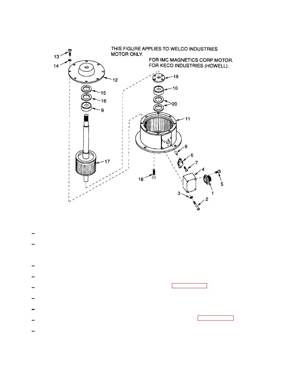
Figure 5-2. Evaporator and Condenser Fan Motor (Welco Industries Motor).
7
Secure connector (1) to terminal box (4) with four screws (5).
8
Secure terminal box (4) to motor with four sets of screws (2) and lock washers (3).
(b) To replace thermal (overload) protector (6):
1
Remove four sets of screws (2) and lock washers (3).
2
Carefully pull terminal box (4) from motor as far as wire leads will allow.
3
Tag and disconnect wire leads from thermal protector (6). (See paragraph 4-26.)
4
Remove two screws (7) and spacers (8). Remove old thermal protector (6).
5
Install new thermal protector (6) onto motor and secure with two screws (7) and spacers (8).
6
See tags and solder leads to new thermal protector (6). Remove tags. (See paragraph 4-26.)
7
Secure terminal box (4) to motor with four sets of screws (2) and lock washers (3).
5-24
