
TM 9-4910-387-14-2
REPAIR
NOTE
Repair is by replacement of authorized parts (TM 9-
4910-387-24P) as required.
NOTE
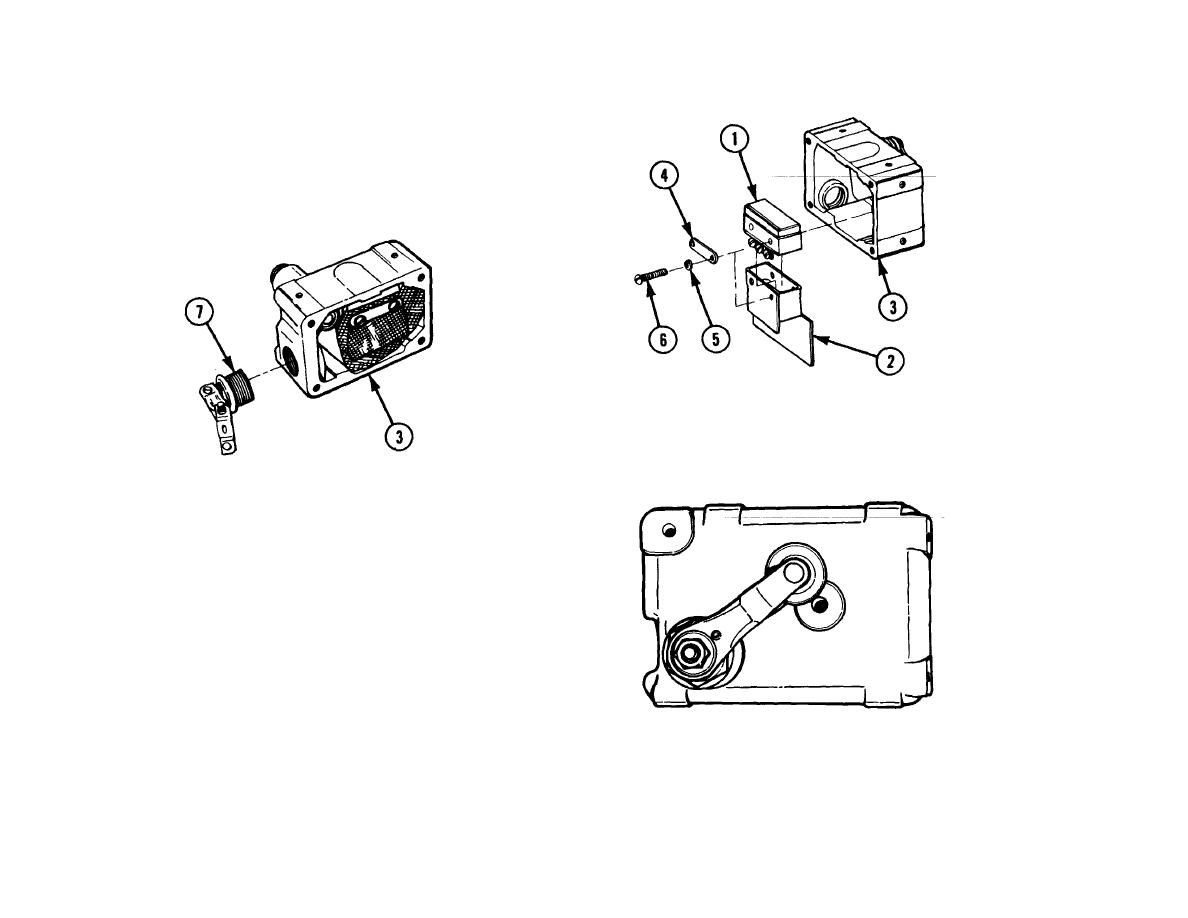
Be sure the roller is alined with the hole in the center of
the switchbox as illustrated.
3 BOX CONNECTOR (7). Install in switchbox (3).
REASSEMBLY/INSTALLATION I
NOTE
Ensure that front flap of holder covers electrical
contacts on microswitch.
1. MICROSWITCH (1). Install in holder (2).
2. MICROSWITCH (1) AND HOLDER (2).
a. Install in switchbox (3).
b. Secure with bracket (4), two washers (5), and two screws (6).
6-449
