TM 9-4910-579-14&P
ADJUSTMENT OF THE MICROMETER
In setting the micrometer to the desired size, it is not necessary to depend on the sense of feel for accuracy;
consequently, the adjustment should be such that there is a noticeable drag when the thimble is turned as
contrasted with the conventional outside mike. The drag is adjustable by means of a hex nut which is accessible by
removing the thimble.
In several instances, the difficulty as to bore sizes has been traced to a loosely adjusted micrometer. Any end play
between the screw and body of the micrometer can affect the size of the bore. If the screw, or spindle, is worn to
the extent that a nice adjustment as to drag cannot be had over the complete range, the micrometer should be
returned to the factory for repair.
After making any adjustment on the micrometer, it should be checked before the machine is used to bore a good
block. Take a light cut, about 1 inch down in a scrapped or demonstrating block, and measure the bore with an
inside micrometer. If the setting of the boring machine micrometer does not compare with the inside mike , loosen
the setscrew in the hub of the thimble of the boring machine mike, turn the thimble to correspond with the measured
size of the hole and lock the setscrew in the thimble.
DEPTH BORING GAGE
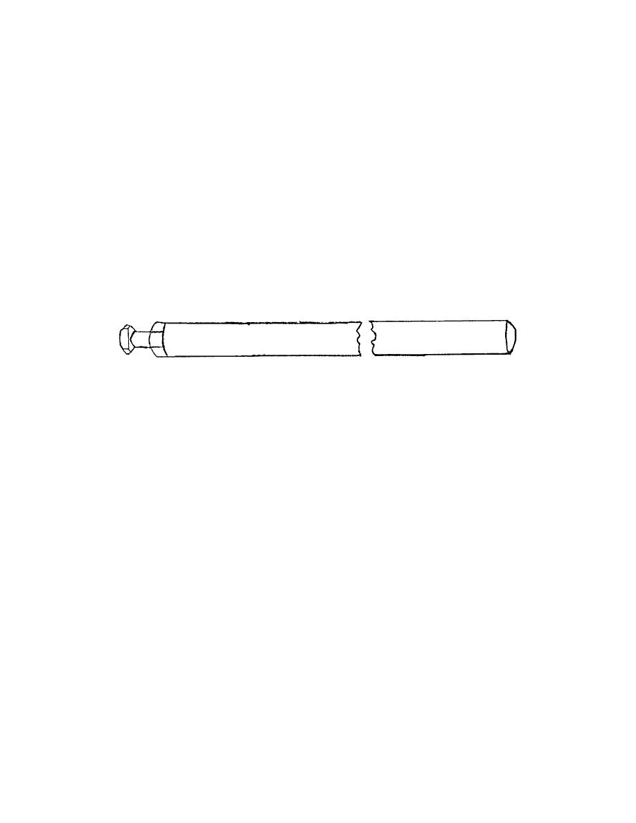
A depth boring gage (roughly sketched above), for use in counterboring, is available for use with Cylinder Boring
Machines. Once adjusted, any number of counterbores of exactly the same depth may be produced. Since the
depth boring gages for the various models of machines are different, it is essential that orders specify with which
machine the depth boring gage is to be used.
The depth boring gage is held in the keyway of the boring sleeve and the sleeve is fed downward manually. The
lower end of the gage contacts the top of the boring machine and the downward travel is stopped when the cast iron
pulley bracket, at the top of the machine, contacts the top of the gage. It is obvious that the depth boring gage must
be adjusted according to the thickness of the flange of the sleeve being installed.
To adjust depth for the sleeve to be installed, first carefully measure thickness of flange at top of sleeve. Select
feeler gages whose total thickness will equal this dimension. With boring sleeve lowered so counterboring tool just
touches top of block, hold depth boring gage in keyway of boring sleeve and insert feeler gages between top of
machine and lower end of gage. Then adjust screw until depth boring gage is tight between feeler gage and casting
at top of sleeve. Lock adjustment with locknut. If a depth micrometer is available, the adjustment may be made by
the cut-and-try method, measuring the depth of the counterbore after each cut, until the correct depth is obtained.
- 24 -

