
TM9-49-35481-14-1
C4
Table 3-16. Tracker Performance Test-Continued
Table 3-16. Tracker Performance Test
STEP
UNIT
PROCEDURE
CORRECTIVE ACTION
STEP
UNIT
PROCEDURE
CORRECTIVE ACTION
4
Rerun the tracker on the TTS.
If good, recoat the cable assembly cases as per TM-9-1430-483-34
NOTE
and replace the bottom cover plate on the tracker. If the tracker still fails any of the BORESIGHT or
MISSILE CMD checks, continue with step 5.
The major units and panels will be identified by the initials as indicated
below.
5
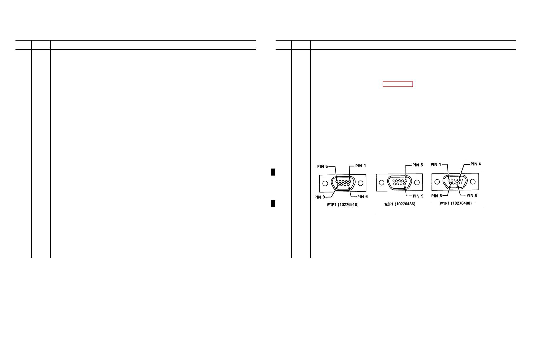
Disconnect WP1 and W2P1 from 3A2A21-J1 and J2. Disconnect W1P1 from 3A2A20-J1.
DMS-D
6
Prepare the DMS-D for testing per paragraph 2-6.
DMM
DIGITAL MULTIMETER
7
PP
MAIN POWER switch to ON.
PP
POWER panel
8
MCP
DMM INPUT switch to DMM INPUT.
MCP
MONITOR/CONTROL panel
9
MCP
DMM FUNCTION switch to K OHMS.
CSCB
CONTROL SIGNAL COMPARATOR BOARD on tracker
10
MCP
DMM LO switch to EXT.
TTS
TRACKER TEST SET
11
Utilizing the following diagram, perform the resistance checks on the cables connected to the tracker by
probing with the DMM pos and neg probes as indicated. If any reading is out of tolerance, proceed to
NOTE
step 34.
This procedure is keyed to be run at D/S or G/S level. If being performed
at D/S level, follow the instructions where <D> is indicated. If at G/S
level, where <G> is indicated.
1
TTS
Perform the tracker operational evaluation as per TM 9-4935-484-14.
If the TRIG OUTPUT check fails, proceed to step 39 in this procedure. If any of the BORESIGHT or
MISSILE CMD checks fail, continue with step 2o
2
Remove the bottom cover plate from the trackers
3
Replace the CSCB as per instructions contained in TM 9-1425-484-24 however - do not perform
recoating procedure at this time.
3-271
