
TM9-4935-481-14-1
C4
Table 3-18. MTS Performance Test
Table 3-18. MTS Performance Test-Continued
STEP
UNIT
PROCEDURE
CORRECTIVE ACTION
STEP
UNIT
PROCEDURE
CORRECTIVE ACTION
NOTE
1
MTS
Perform the battery charging procedure as per TM 9-6920-484-12. Check all three possible external
power source inputs. Leave the set connect to the 105/130 Vac source when checks are completed
The major units and panels will be identified by the initials as
(W4 cable) and W1 cable. Troubleshoot as per schematics in TM 9-6920-483-34-1. Replace BCR or
indicated below.
batteries if required.
DMS-D
NOTE
DMM
DIGITAL MULTIMETER
Perform (1)any time a new or/repaired BCR is installed in the
MTS.
CT
COUNTER-TIMER
2
BCR
EXTERNAL switch to AC.
PP
POWER panel
3
BCR
INTERNAL switch to OFF.
MCP
MONITOR/CONTROL panel
4
BCR
METER switch to OFF.
CIP
COUNTER INHIBIT(SEC) panel
5
Prepare the DMS-D for testing per paragraph 2-6.
TP
TRAINER panel
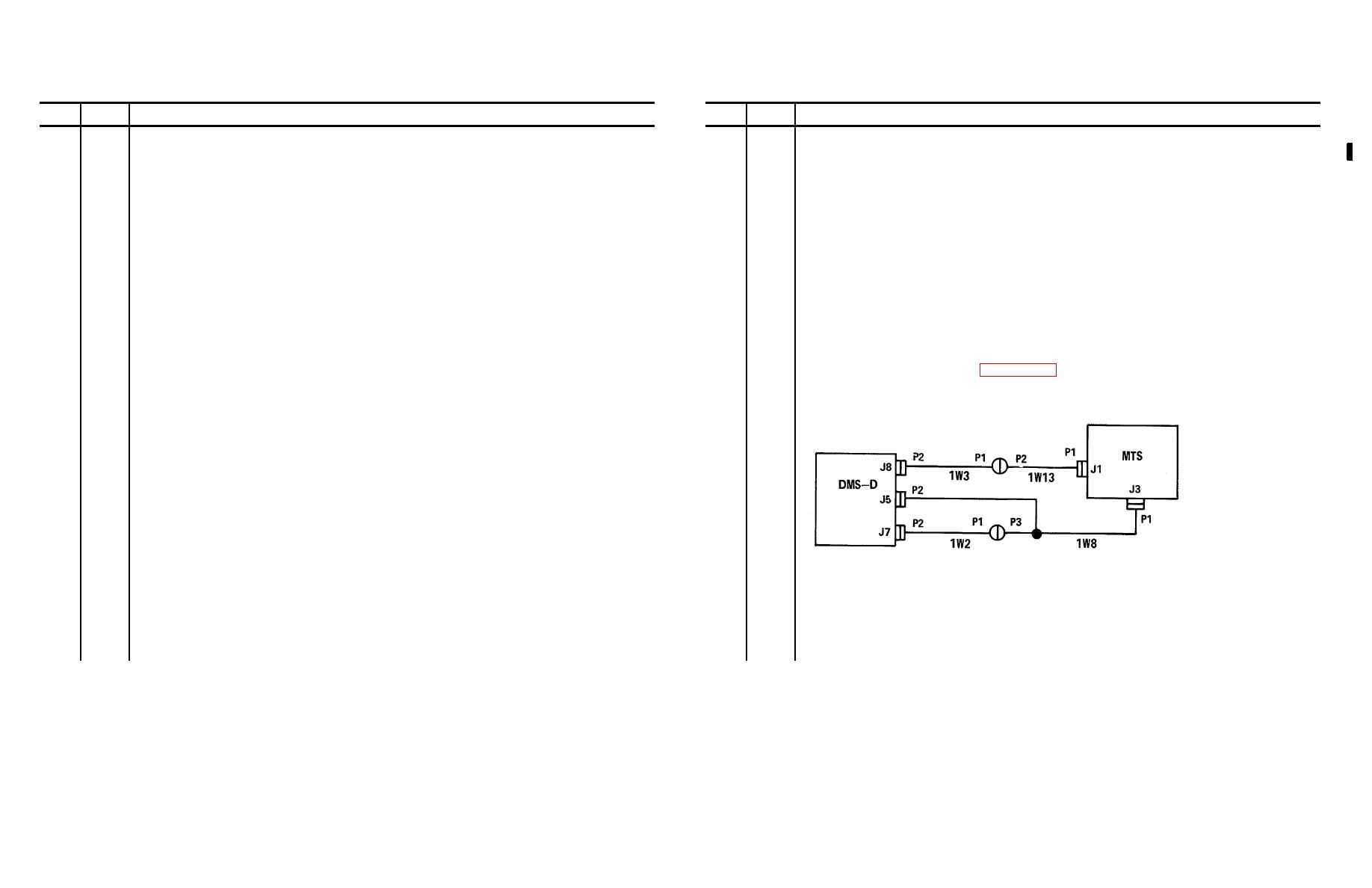
6
Connect the DMS-D and MTS as depicted below.
PPE
PROG PERFORM EVAL panel
PD
PEAK DETECTOR panel
OSC
OSCILLOSCOPE (AN/USM-338)
MTS
MONITORING SET
BCR
BATTERY CHARGER REGULATOR
NOTE
For fault isolation where marked by a ( ), see pages at the end of
this table.
Otherwise refer to schematic diagram and
components location in TM4 9-6920-483-34-1.
3-277
