Home
Download PDF
Order CD-ROM
Order in Print
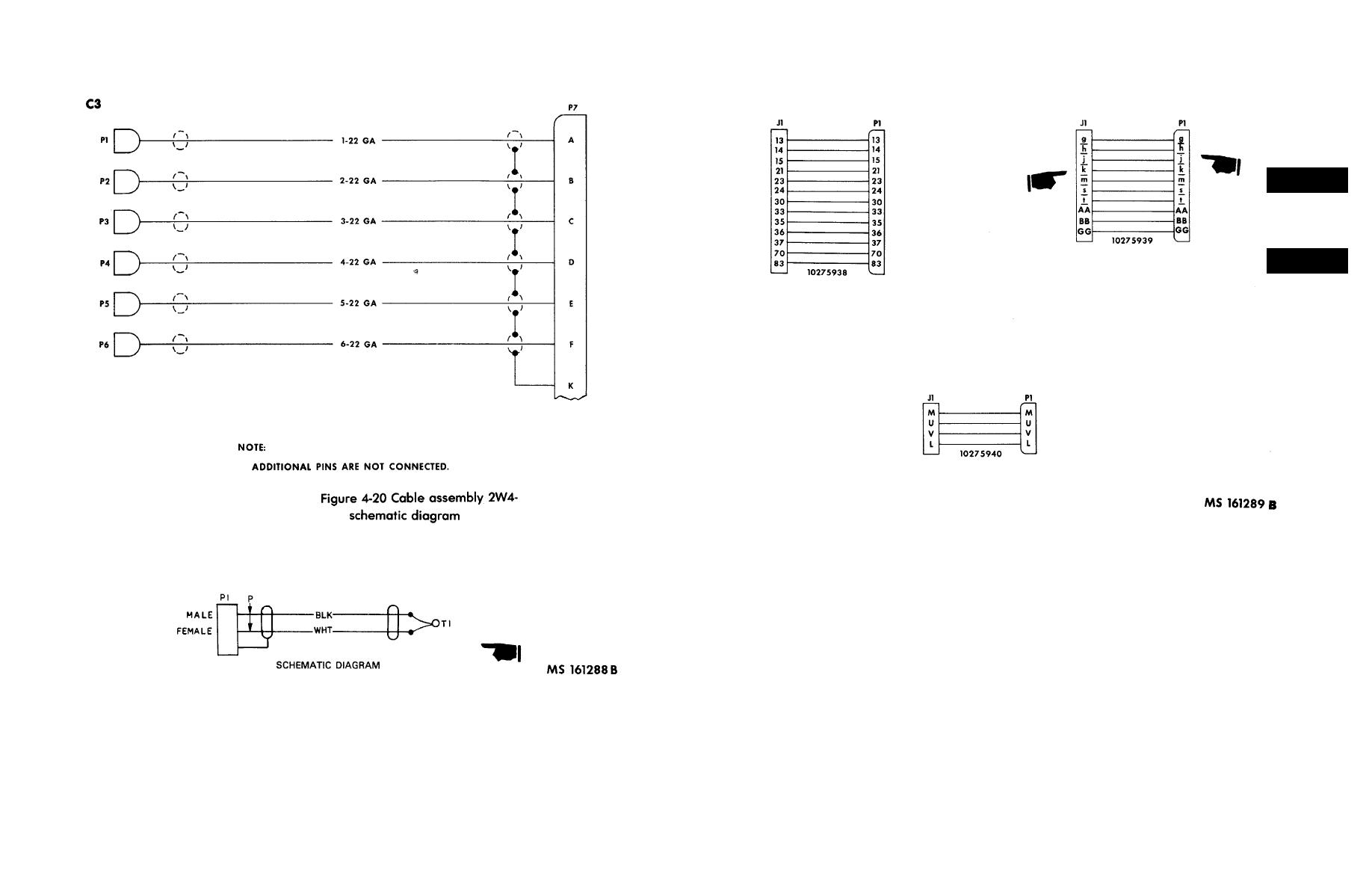
Figure 4-19. Cable assembly 2W3 schematic diagram
Figure 4-22. 'E' Cell sync adapter (10275038)-schematic diagram
TM-9-4935-481-14-2 Dragon Maintenance Set Manual
Page Navigation
13
14
15
16
17
18
19
20
21
22
23
TM
9-4935-481-14-2
Figure
4-21.
Test
adapters
schematic
diagram
Figure
4-20.1
Cable
Assembly
1W21
schematic
diagram
4-29
/
(4-30
Blank)