
TM 55-4920-390-13&P
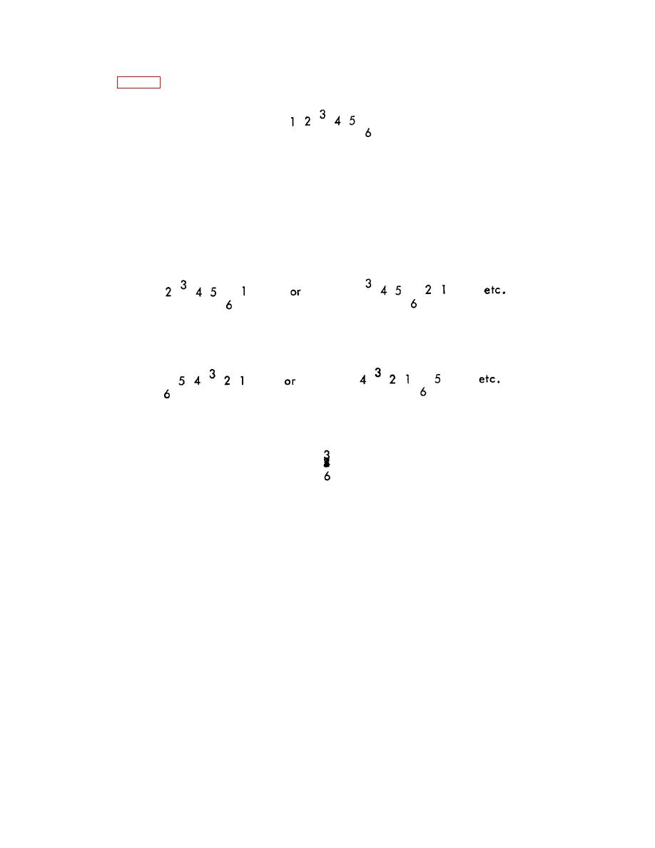
g) With the targets thus displayed, the operator may make judgments of track and lead-lag. A typical display might
be as in Fig. 4-2.
Figure 4-2. Typical Blade Pattern.
Assuming the numbers are about an inch high, this would indicate blade 3 to be about 1/2" high and 6 about an
inch low. It also indicates that lead-lag is OK.
h) A similar pattern can be seen at "n" equally spaced points in azimuth around the "disc" described by the blade
tips (assuming "n" blades). Keep in mind that the display will appear with the numbers in a different sequence
when viewed at a different point in azimuth, such as -
i) Further, depending on the "sense" of the "error" (or spread of the numbers) introduced by means of the vernier,
the numbers may be reversed, as
j) Precise adjustment of the vernier to achieve exact synchronization will "stack" the numbers as
k) Any of these situations are useable and acceptable, and the choice of the optimum display should be left to the
individual observer. The best display may change from one situation to another.
4-7

