
TM9-2330-207-14
4-39. MAINTENANCE AND ADJUSTMENTS (Cont)
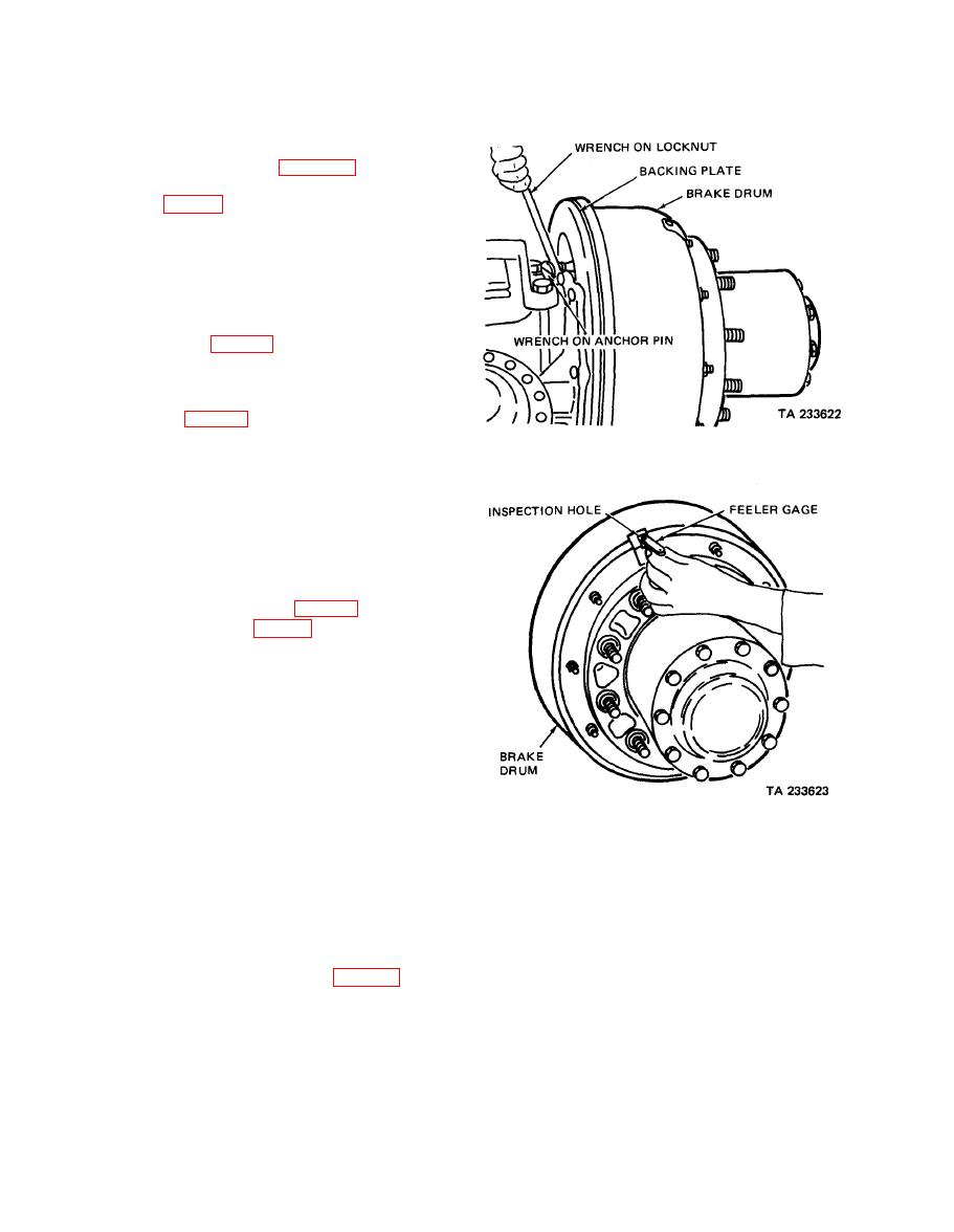
(b) Major adjustment (figs. 4-43 and 4-44).
Wheels must be removed from hub
ment to give access to inspection hole
in drum.
1.
Remove nut and Iockwasher which
secure inspection hole cover over
inspection hole in brake drum.
Loosen locknut on brake shoe anchor
2.
pin (fig.4-43). Rotate brake drum
until opening is 1 inch from end
of one brake lining, nearest anchor
pin. Insert 0.005-inch feeler gage
and brake lining and with wrench,
turn anchor pin until 0.005-inch
clearance is obtained. Hold anchor
pin with one wrench and with a
second wrench tighten locknut.
Check clearance again.
Rotate drum until inspection hole is
3.
1 inch from other end of same brake
shoe, nearest camshaft. Insert 0.010-
inch feeler gage (fig. 4-44) and turn
worm shaft (fig. 4-42) of slack ad-
juster until 0.010-inch clearance is
obtained. Recheck clearance (2 above)
at other end of brakeshoe.
4.
Repeat procedure outlined in 2 and 3
above on each hole of each brake.
Check all anchor pin locknuts and
make certain worm shaft of each
slack adjuster is locked.
(3) All Models except M127.
feeler gage (Model M127)
(a) General. Two adjusting shafts protrude from back of brake spider and dust shield enclosure
of the brake assembly. Each shaft provides the lining clearance adjustment for one brake
shoe.
(b) Brake lining clearance adjustment.
1.
Release brakes on towing vehicle. Jack up axle so that wheels may be rotated freely.
2.
Engage adjusting shaft (fig. 4-45) with a 3/8-inch socket wrench. Rotate shaft in direction
of forward wheel rotation to decrease brake lining clearance until lining drags on drum.
Check drag on drum by rotating wheel in forward direction of rotation. Make a brake
application to be certain shoes are centered; adjust as required.
4-64

