
TM 9-2330-271-14&P
a.
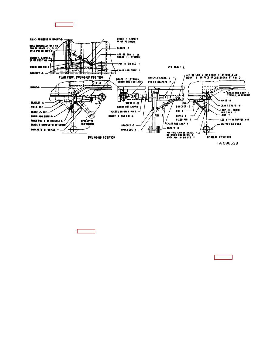
Operation (fig. 2-4).
Figure 2-4. Operation and swing-up procedures.
(1) With landing gears in normal operating
(1) Using crank (L), retract leg (X)
position with legs contacting ground, unfasten snap and
approximately 12 inches. Replace crank (L) in stowed
chain assembly (N). Remove crank (L) from stowage
position on brace (F).
Refasten snap and chain
socket (M).
assembly (N).
(2) Position slot in crank (L) to engage pin in
(2) Remove pin (A) from small brace.
shaft (W).
Remove pins (B and C) from large brace (F). This is the
(3) Landing gears are two speed separately
brace with the crank stowed on it. Fasten small brace to
operated landing legs.
leg assembly with snap and chain assembly (K).
(4) Pull out shaft (W) for speed travel.
(3) Pick up brace (F) with crank (L) stowed on
(5) Push in shaft (W) for low speed travel.
it. Turn brace end for end (plan view). Aft end (Z) is now
(6) Set ratchet on crank (L) to raise or lower
at forward end near pin (B). Place end hole around pin
trailer. Clockwise rotation raises van. Counterclockwise
on bracket (P).
rotation lowers van.
(4) Manually lift each leg assembly carefully
b. Swing-Up Procedure (fig. 2-4).
to horizontal position. Attach snap and chain assembly
(J) to hold each leg. Aline hole in end (Z) of brace (F) on
top of (not between) brackets (R) on leg assembly (Y).
NOTE
(5) Insert pin (B) to secure each landing gear
Swing landing gear to horizontal position
and brace in wing-up position.
for aircraft loading only.
c. Swing-Down Procedure (fig. 2-4).
(1) Remove pin (B).
WARNING
(2) Remove snap and chain assembly (J)
which secures each leg.
Semitrailer must be supported on the K-
(3) Carefully and slowly allow leg to extend to
loader. Be sure all toggle pins have
the vertical position.
been lubricated with GAA grease and
(4) Position brace (F) with crank (L) stowed
are operable and removable.
on it, making certain to turn it end for end to the position
is occupied prior to performance of step (3) above.
2-4

