
TM 9-2330-271-14&P
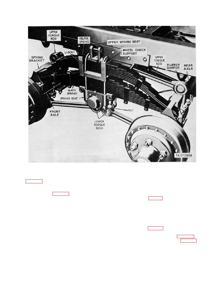
Figure 4-39. Tandem suspension system-installed view.
(6) Loosen, but do not remove, two cap
cedure in paragraph a above. Torque U-bolt nuts to 225-
screws (fig. 4-38) which clamp lower spring bracket to
280 lb-ft.
main spring assembly.
(7) Move main spring assembly, spacer and
4-54. Spring Seat
helper spring assembly (fig. 4-39) as a unit toward the
rear of the semitrailer until the front end of the springs
a.
Removal (fig. 26)
clears the front axle spring bracket
NOTE
(8) Remove helper spring assembly by lifting
The key letters shown below in
front end of spring up and forward far enough for rear
parentheses refer to figure E-26 except
end of spring to clear rear axle bracket.
where otherwise indicated.
(9) Remove spacer and support by lifting up
(1) Support weight of semitrailer by jacking up
and away from top of main spring assembly.
axle and bracket assembly at end from which spring seat
(10) Remove main spring assembly by the
is to be removed. (fig 4-39).
same procedure used for removal of helper spring
(2) Remove four nuts and lock washers from
assembly (step 8 above).
two U-bolts and remove U-bolts (fig. 4-39). Lift off
c. Installation.
Install spring assemblies and
spring seat on top of spring assembly (fig. 4-39).
component parts in the reverse order of the pro-
4-57

