
TM 9-2330-356-14
is on its compression stroke, which follows the closing of
h.
Disconnect pressure gage from Number 1
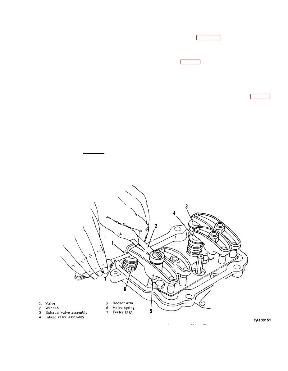
its intake valve. See figure 7-80 for identification of intake
cylinder nozzle and holder assembly. Attach fuel inlet and
valve assembly.
return lines, and then repeat above procedures to test and
adjust Number 2 cylinder nozzle and holder assembly.
(2) Continue clockwise rotation until TC (top
i. Repeat step h for Number 3 and Number 4
center) mark on flywheel lines up with timing pointer on
cylinder nozzle and holder assemblies.
gear cover (fig. 7-78). Then turn flywheel in a clockwise
direction for an additional 10-450. The timing mark for
this position must be established. In this position, the
piston will be in its power stroke with both valves
NOTE
completely closed.
Readjust rocker arm-to-valve clearance after
(3) Using a feeler gage, check the clearance
the first 50 hours of operation on a new or
between the rocker arm and the valve stem cap (fig. 7-80).
rebuilt engine.
Increase or reduce the clearance until the proper gap is
established, adjusting the lock nut which secures the
a.
Check and adjust the rocker arm to proper valve
rocker arm to the cylinder head. Correct valve clearance is
clearance every 500 operating hours.
0.009-inch for intake valves and 0.007-inch for exhaust
valves.
b.
Always check and adjust the valve tappet
clearance when the engine is at an ambient temperature
(4) To adjust the valve clearance for Number 2
of approximately 70F. Remove rocker cover and proceed
cylinder, turn the blower wheel clockwise 180 until the
as follows:
flywheel is 10-450 past the BC (bottom center) mark and
adjust valves as given in step (3).
CAUTION
Turn blower wheel clockwise only.
Equipment
Remove shroud door panel on engine to gain
a.
(1) Using a 5/8-inch socket wrench and extension,
access to the air intake manifold.
turn the blower wheel clockwise until Number 1 cylinder

