
TM 9-4120-371-14
(2) Use a multimeter set to AC voltage range of at least 250 volts for following tests.
(3) Measure voltage between pin D of connector P1 and a good chassis ground. Voltage must be zero
(0). If more than zero voltage is observed, disconnect cable and check power source, correct problem at power
source or at cable connection as indicated.
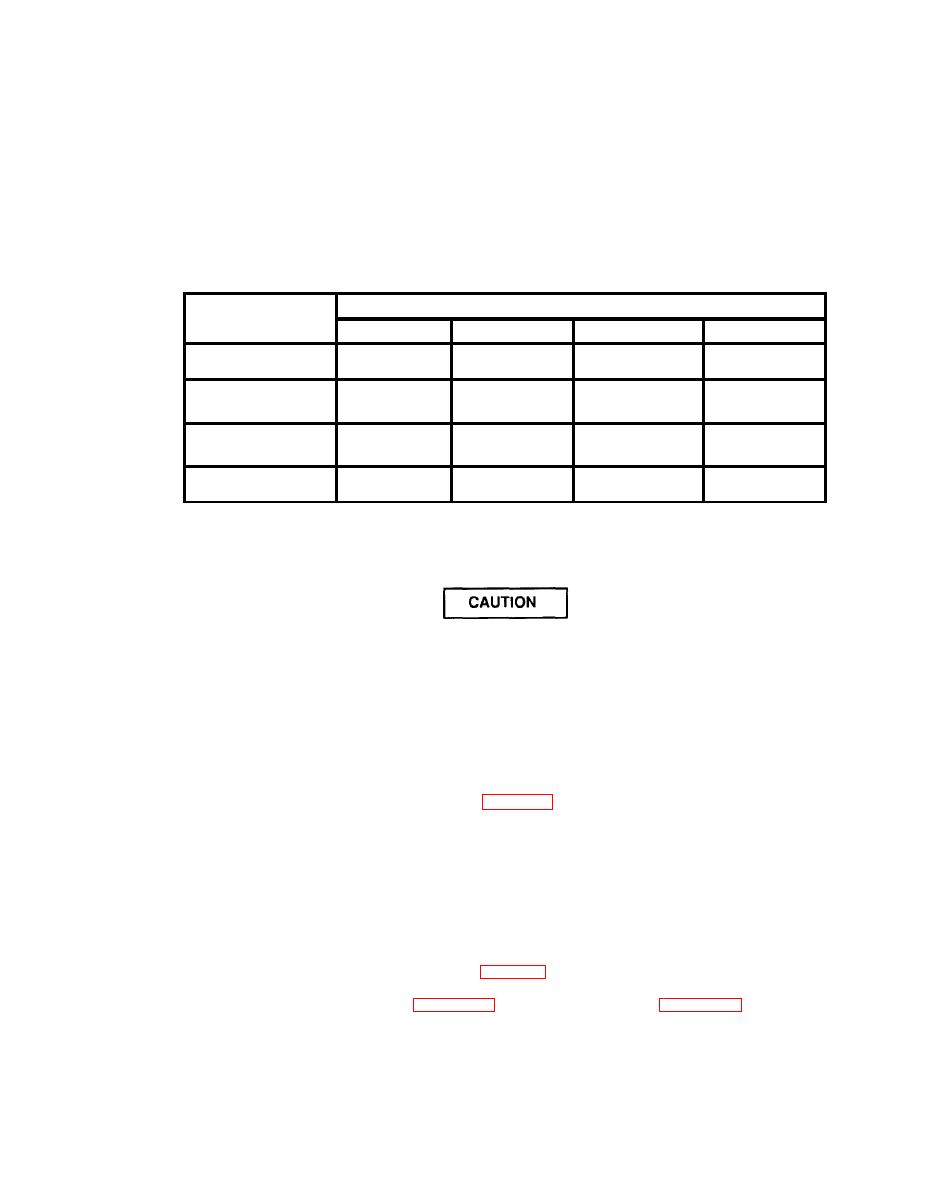
(4) With zero voltage on pin D of P1 connector, check voltages between remaining pins as shown on
following chart.
P1 CONNECTOR
To Pin
Measure
from Pin
A
B
c
D
A
N/A
208
208
120
B
120
208
208
N/A
C
208
208
N/A
120
120
D
120
N/A
120
Voltages should be approximately as shown. If voltages are not within ten volts of those indicated on chart,
disconnect power. Locate and correct problem.
Check that mode selector switch is OFF
(5) After proper. voltages are indicated on all pins of connector P1, connect P1 to connector J1 on air
conditioner.
NOTE
The following steps require two people. One must be at control panel. The other must be in
position at rear of air conditioner to see condenser fan rotation. (Condenser fan can be
seen through condenser air outlet grille, figure 12, item 16.)
(6) The person at control panel should turn mode selector switch to VENT and immediately back to
OFF.
(7) The person at rear of unit should watch condenser fan to determine direction of rotation. Fan blades
must turn toward grille.
(8) If fan blades turn away from grille, unit power cable is not connected properly. Exchange wires
connected to pins A and B at power source connection and repeat steps (6) and (7) above.
(9) Check unit operation in accordance with para 2-6 and 2-7.
i. See air conditioner wiring diagram, figure 423, and electrical schematic, figure 4-24, for additional
wiring information.
4-27

