
TM 9-4120-388-14
b. Removal
a. Inspection/Test
This task consists of:
c. Installation
INITIAL SET-UP:
Junction box removed (4-46).
Junction box cover removed (4-47).
a. Inspection/Test.
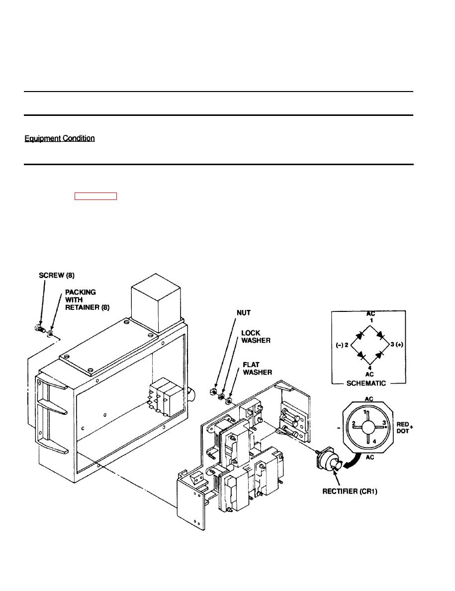
Be sure that wire leads are property connected to rectifier and are not damaged. See wiring diagram
(1)
If rectifier is suspected bad, tag and remove rectifier lead.
(2)
Use a continuity tester or a multimeter set on the lowest OHMS scale to test for continuity between each
(3)
of the four rectifier terminals and mounting plate. If continuity is found between any rectifier terminal and
mounting plate, replace rectifier.
(4)
Use a multimeter set on lowest OHMS scale to test resistance across rectifier bridge in accordance with
the following table. If resistance is different from that indicated in table, replace rectifier.

