
TM 9-4120-407-14
3-20. CONTROL PANEL ASSEMBLY REPAIR AND REPLACEMENT. (Cont)
b.
Disassembly
NOTE
Disassemble only to extent necessary for repair.
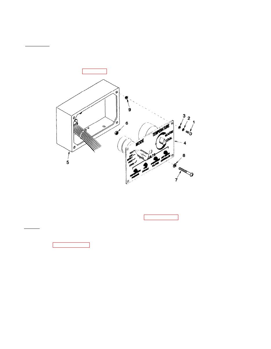
(1) Remove four screws (1) Figure 3-28, lock washers (2), and flat washers (3). Discard lock washers.
Figure 3-28. Control Panel Assembly
(2) Carefully pull control panel (4) away from control box (5) as far as wiring harness will allow.
(3) Remove self locking nut (6), screw (7), and flat washer (8). Discard self locking nut.
(4) Remove wiring harness and individual components per paragraphs 3-21 through 3-24.
c . Repair
NOTE
individual control panel assembly components.
(1) Replace any damaged or missing components or hardware.
(2) Replace clinch nuts (9) if stripped or missing.
(a) Remove damaged clinch nuts (9).
(b) Install new clinch nuts (9) using clinch nut installation tool.
(3) Touch-up or re-paint the control box (5) in accordance with TM 43-0139.
3-86

