
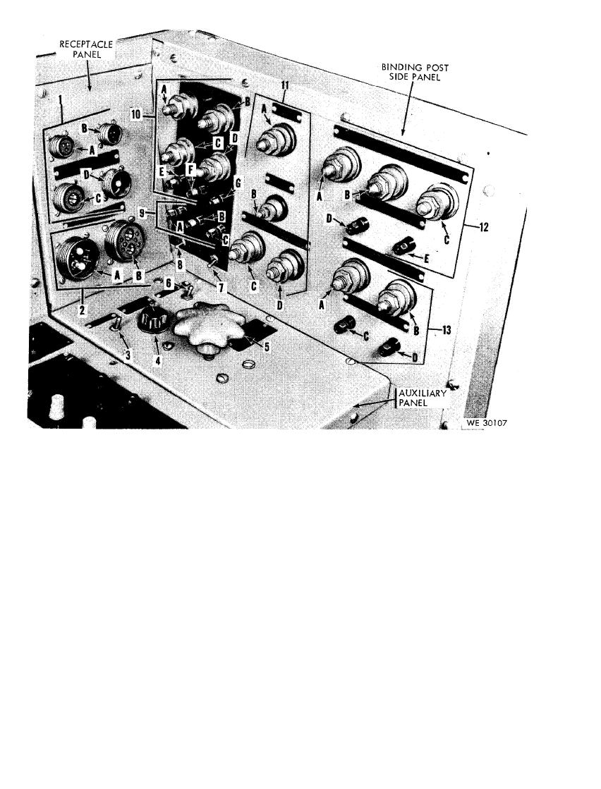
C - No. G+ binding post
1-150-ampere generator control box receptacles
D - No. G- binding post
A - No. 5 receptacle
E - Ground (grid) binding post
B - No. 6 receptacle
F - No. D binding post
C - No. 3 receptacle
G - No. F-B binding post
D - No. 1 receptacle
11 - Starter binding posts
2 - 4 0 0 - a m p e r e generator control box receptacles
A - Input binding post
A - Generator receptacle
B - Free-run binding post
B - Battery receptacle
C - Common binding post
3 - Auxiliary start momentary-on switch
D - Stall torque binding post
4 - Voltage adjusting rheostat
12 - Alternator input binding posts
5 - Starter carbon rheostat
A - No. T1 binding post
6 - Field shorting switch
B - No. T2 binding post
7 - Ignition switch (ign sw)
C - No. T3 binding post
8 - Equalizer coil test switch
D - No. D binding post
9 - AC/dc system binding posts
E - No. E binding post
A - No. D binding post
13 - Generator input binding posts
B - No. E binding post
A - No. G+ binding post
C - Ignition switch (ign sw) binding post
B - No. G- binding post
10 - Regulator binding post
C - No. D binding post
A - No. B+ binding post
D - No. F binding post
B - No. B- binding post
34

