INSTALLATION AND PREOPERATIONAL PROCEDURES
Section I. INSTALLATION, CONNECTION, AND TESTING OF INSTALLED EQUIPMENT
9. General
(4) Use a device capable of lifting
3,000 pounds to remove the shel-
a. When an AN/MSC-31 is received,
ter from the base of the crate.
uncrate and check it (para 10), and then
Attach the sling assembly to the
perform the tests in paragraph 13. When
lifting eyes on the top corners of
an S-183/MSC-31 (para 7a and 8) is re-
the shelter (para 15) and raise the
ceived, perform the procedures in (1)
shelter off the base of the crate.
through (4) below.
(5) Remove the base of the crate and
(1) Uncrate and check the equipment
lower the shelter.
b. Checking Shelter Contents. Check
(2) Install the SB-22(*)/PT (para 11).
the contents of the shelter against the
(3) Install the TA-312/PT (para 12).
packing list. If the packing list is not
(4) Test the equipment after installa-
available, use the table of components
tion (para 13) .
b. The signal duct contains all the wir-
probably was packed.
ing required to connect the SB-22(*)/PT ,
the TA-312/PT, and the LS-147(*)/FI to
PT
the external lines. All wiring is appropri-
a. Remove the front cover of the SB-
ately marked and prepared for connection.
22(*)/PT (TM 11-5805-262-12).
The signal schematic wiring diagram (fig.
b. Remove the headset-handset from
the front cover and store the cover.
the connection procedures. The power
c. Open the rear cover of the SB-22(*)/
duct contains power receptacles appropri-
ately marked for each piece of equipment
PT.
d. Install four Batteries BA-30 in the
that requires ac power.
battery case and ground the SB-22(*)/PT.
for installation and connection of com-
Note. Connect the SB-22(*)/PT ground lead to
ponents.
the ground terminal adjacent to the INTERCOM re-
ceptacle (fig. 1 1).
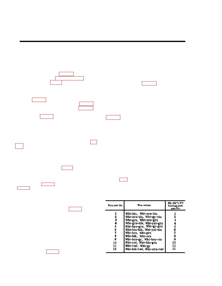
e. Connect the prepared leads from the
SB-22(*)/PT cable stub to the SB-22(*)/
PT binding posts according to the chart
the convenience receptacles.
below.
(1.) Remove the panels of the crate by
removing the bolts. First remove
the front and rear panels; then
remove the top and side panels.
(2) Remove the lag screws that secure
the base of the crate to the shel-
ter.
(3) Remove the sling assembly from
its package on the floor of the
shelter (fig. 15).


