TM 11-5895-463-15
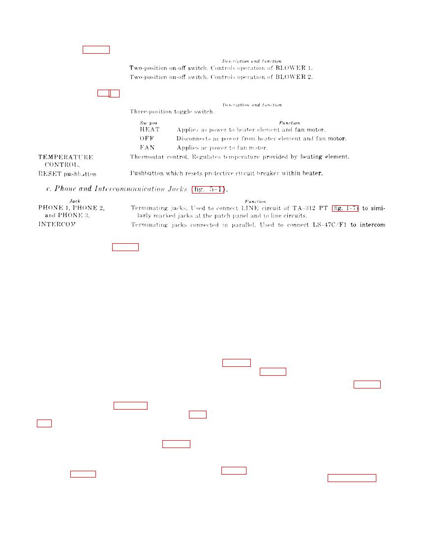
Control. indicator, or instrument
BLOWER 1 switch
BLOWER 2 switch
Control, indicator, or instrument
HEAT-OFF-FAN switch
line between shelthers.
Control. indicator, or instrument
Description and function
ON-FAN-COOL
selector switch.
Function
SW POS
COOL
Applies ac power to compressor motor.
Disconnects ac power from compressor motor and fan.
OFF
FAN
Applies aC power to fan motor.
Thermostate control, Regulates temperature provided By SELECTOR switch setting.
THERMOSTAT
FRESH AIR control
Controls intake of fresh air to interior of shelter.
d. Operate circuit breaker switch No. 1
(LIGHTS) to ON.
Warning: To prevent asphyixation, the AN/
e. Operate LIGHT 1 and LIGHT 2 switches
MSC-31A must be ventilated at all times
when occupied.
light switch (fig. 5-1) to ON as required.
Prepare the AN/MSC-31A for full operation
as follows:
indicates 105 to 125 volts ac.
a. Connect the AN/MSC-31A to the avail-
able power source (para 2-3 and 2-4); the
approximately O ampere.
P O W E R INDICATOR NEON LAMP (fig.
51) will light.
h. Operate circuit breakers No. 2 through 7
to ON.
b. Operate the MAIN circuit breaker switch
on the power distribution panel (fig. 1-6) to
ON.
Note. Refer to the applicable technical manuals
c.
Operate
the
BLACKOUT-BY-PASS
switch (fig. 5-1) to ON. When blackout con-
munications components. Refer to paragraph 3-1 for
ditions are required, operate the switch to
(Inscriptions and functions of controls and indicators
OFF.
of the AN/MSC31A components.


