TM 55-1925-282-14&P
0014 00
1
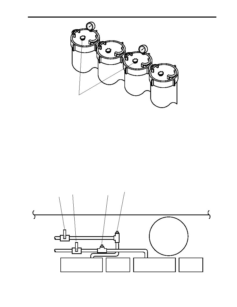
Figure 7. ROWPU Filters
7. Remove the two plugs (figure 8, items 1 and 2) located upstream of valves RO-V-1-2 (figure 8, item 3) and
RO-V-2-2 (figure 8, item 4), and attach an 8-foot (2.4 meter) cleaning hose to each exposed connection.
8. Connect the third 8-foot (2.4 meter) cleaning hose to the cleaning supply inlet (figure 9, item 1).
9. Place the opposite ends of the three cleaning hoses in the bucket with the prepared cleaning solution.
2
3
1
4
ENGINE ROOM
AMS-2
MEDIA
FILTER
ROWPU 2
ROWPU 1
ROWPU 2
ROWPU 1
SYSTEM
SYSTEM
FLOW CONTROL PANEL
FLOW CONTROL PANEL
CONTROLLER
CONTROLLER
Figure 8. Cleaning Solution Valves and Fittings
0014 00-7

